
More than 50% of building issues happen because of design mistakes or lack of proper inspection. This shows how important it is to plan carefully and check every detail in construction.
A foundation plan drawing helps prevent these problems by giving a clear layout of the foundation. It includes important details like footings, columns, walls, and reinforcement to ensure the structure is strong and safe. With a well-prepared foundation plan, construction teams can avoid errors, build confidently, and meet all design and safety standards.
In this article, you’ll learn about the purpose, types, and essential details of foundation plan drawings, along with step-by-step instructions on creating and reading them effectively.
What are Foundation Plan Drawings?

A foundation plan drawing is a detailed diagram that shows how a building’s foundation will be built. It includes important information like the size, shape, and materials needed to support the structure. These drawings help ensure that the weight of the building is evenly spread across the ground, preventing problems like cracks or sinking.
The drawing plan usually includes details such as:
- The type of foundation (slab, crawl space, or basement)
- The depth, level and width of the footings
- The placement of beams and columns
- Reinforcement materials like steel bars
These details ensure the building is strong and stable and help construction teams follow safety rules and local building codes while working on the project.
While foundation plans lay the groundwork for a building’s stability, they are often confused with basement plans. Although both deal with the lower sections of a structure, they serve different purposes and contain distinct details.
Comparison of Foundation Plan & Basement Plan
Foundation plans and basement plans both focus on the lower part of a building, but they have different purposes.
A foundation plan shows the structural elements that support the building and ensures the building stays strong and stable. On the other hand, a basement plan is a detailed layout of the basement area.
Knowing the difference helps avoid confusion, especially when building or renovating, and ensures the foundation and basement are correctly designed. Below are the differences between the foundation and basement plans:
| Aspects | Foundation Plan | Basement Plan |
| Purpose | Shows the structural base of the building, including foundations and footings. | Focuses on the layout and design of the basement area, including walls, windows, and stairs. |
| Location in Building | Typically shown at ground level or below the first floor. | Located below the first floor, directly beneath the main structure. |
| Details Provided | Footings, foundation walls, support columns, and concrete slab or crawl spaces. | Layout of the basement, including rooms, walls, columns, windows, and access points. |
| Level of Detail | Provides a structural overview of support and stability elements. | Provides a functional design, showing usable space and potential rooms or utilities. |
| Structural Focus | Emphasis on the strength and stability of the building’s base. | Focus on spatial arrangement and accessibility of basement areas. |
| Use in Construction | Guides the construction of the foundation and supports the overall structure. | Used for designing basement living or storage spaces, and considering plumbing or HVAC installations. |
| Primary Function | To ensure the building’s foundation is properly designed and strong enough for load-bearing. | To plan and optimise the basement space for intended purposes (e.g., storage, living, utilities). |
| Typical Features | Slab, crawl space, or basement foundation; footings; foundation walls. | Rooms, storage spaces, stairways, windows, plumbing, and electrical systems. |
Knowing the differences between foundation plans and basement plans helps architects, engineers, and builders make informed decisions during the design and construction process. But beyond comparison, it’s also important to understand how foundation plan drawings are applied in real-world projects.
Also read: Importance of Construction Drawings: Types, Details & Regulations.
Application of Foundation Plan Drawings
A foundation plan drawing is an essential part of construction plans, acting as a guide for building a strong and stable base. It shows important details like the size of footings, placement of columns, thickness of slabs, and reinforcement needed.
These drawings help ensure that the foundation can hold the entire structure safely. Architects, engineers, and contractors use them to plan excavation, choose the right materials, and organise the construction process efficiently.
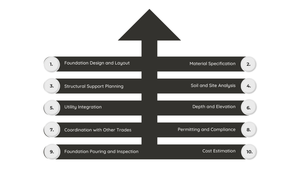
Foundation plan drawings are essential in construction for:
- Foundation Design and Layout: They show the exact size and position of the foundation, ensuring it matches the building’s design and structural needs.
- Material Specification: These plans list materials like concrete and steel reinforcement, helping builders source the right materials.
- Structural Support Planning: They indicate where footings, columns, walls, and beams should be placed to support the building properly.
- Soil and Site Analysis: Some plans include soil details, such as its strength and stability, to ensure the foundation is suitable for the site.
- Utility Integration: They show where drainage, water lines, and electrical conduits should go, ensuring these systems are properly built into the foundation.
- Depth and Elevation: The plans specify how deep the foundation should be and any height differences needed for the terrain.
- Coordination with Other Trades: Contractors and subcontractors use these drawings to align foundation work with plumbing, electrical, and framing systems.
- Permitting and Compliance: They are required for building permits and ensure the foundation meets local safety and building codes.
- Foundation Pouring and Inspection: The drawings guide workers during construction and help inspectors check if the foundation follows the approved design.
- Cost Estimation: Builders use them to calculate material and labour costs for the foundation phase.
By providing clear and detailed information, foundation plan drawings help ensure a strong, stable, and well-coordinated construction process. However, to fully understand how foundation plan drawings contribute to a successful build, it’s important to break down their key components.
Ready to simplify your projects and achieve these benefits?
BIM ASSOCIATES is your one-stop BIM Solution provider for Revit Architectural and Structural Solutions. They coordinate with your team to develop, record, and streamline the BIM Revit Model, along with the sheets, Bill of Quantities, Bill of Materials, and clash coordination.
Components of Foundation Plan Drawings
A foundation plan drawing includes several key components that ensure the structure is properly supported and built to last. These elements provide detailed information on the layout, materials, and structural requirements of the foundation.
By understanding each component, architects, engineers, and builders can ensure accuracy in construction, compliance with building codes, and long-term stability. Below are the essential components found in foundation plan drawings:
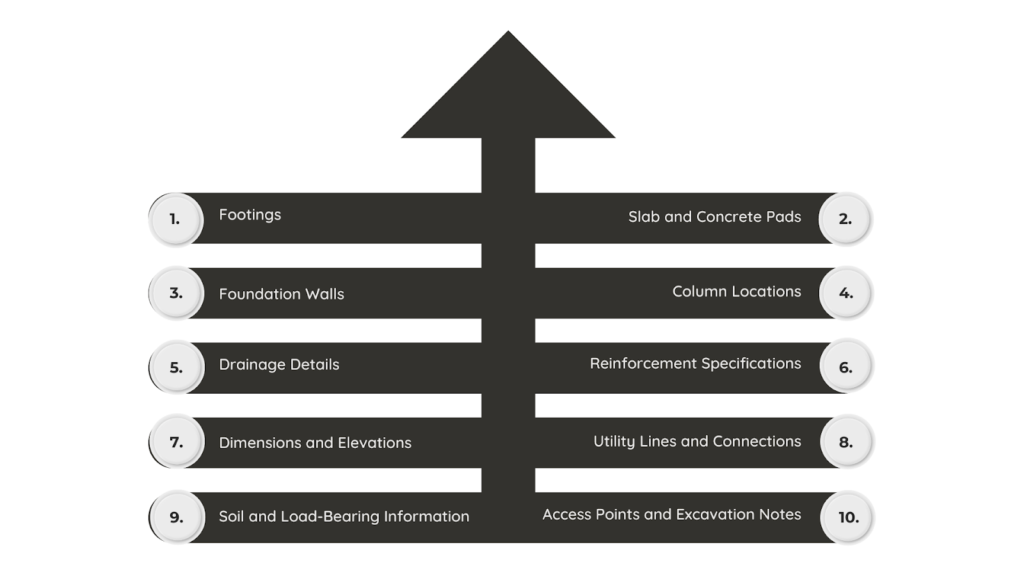
- Footings
Footings are the base of the foundation that helps to distribute the building’s weight evenly on the ground. The plan shows their size, location, and type and is designed based on the soil and the building’s load.
- Slab and Concrete Pads
If the building has a concrete slab foundation, the plan details its thickness, dimensions, and any additional concrete pads needed to support heavy structural elements.
- Foundation Walls
These are vertical walls that connect the footings to the rest of the structure. The plan includes height, thickness, materials (such as concrete or masonry), and reinforcement details.
- Column Locations
If the foundation includes columns, the plan marks their placement, size, and material. This ensures they are positioned correctly to support the structure above.
- Drainage Details
To prevent water damage, the plan includes drainage solutions like French drains, sump pumps, or weeping tiles. These systems help keep the foundation dry and protected.
- Reinforcement Specifications
Foundations need extra strength to prevent cracks and shifting. The plan shows where steel reinforcements (such as rebars or mesh) should be placed, along with their size and spacing.
- Dimensions and Elevations
Exact measurements are crucial for accuracy. The plan provides dimensions for footings, walls, and columns and elevation markers to indicate foundation height and depth.
- Utility Lines and Connections
The plan includes the placement of essential utilities like water, sewer, gas, and electricity, ensuring they pass through or under the foundation without causing issues.
- Soil and Load-Bearing Information
Understanding the soil type helps in designing a stable foundation. The plan may include notes on soil conditions and how they impact the foundation’s design and depth.
- Access Points and Excavation Notes
If the foundation includes doors, windows, or access points (such as basement entries), these are marked in the plan. Excavation details, like soil removal and site preparation, may also be included.
Every part of a foundation plan is important for keeping the structure strong, stable, and safe. The design of these plans depends on the type of building, with each plan customised to meet specific structural needs and ensure long-term durability.
Types of Foundation Plan Drawings
Foundation plan drawings come in different types, each designed for specific construction needs. The type of foundation used depends on factors like soil conditions, building load, and design requirements.
These drawings provide detailed layouts and specifications to ensure the foundation is built correctly and supports the structure properly. Below are the common types of foundation plan drawings used in construction:
| Types | Details | Key Features |
| Slab-on-Grade Foundation Plan | A concrete slab placed directly on the ground, commonly used for single-story homes in warm areas. | Slab layout and thicknessPlacement of reinforcement (rebar)Control and expansion joints |
| Crawl Space Foundation Plan | A raised foundation with short walls, creating a small open space underneath the building. | Layout of foundation walls, piers, and beamsCrawl space height and ventilation openingsAccess points for maintenance |
| Full Basement Foundation Plan | A deep foundation that creates a basement, which can be used for storage or living space. | Layout of basement walls, columns, and floorsPlacement of windows, doors, and drainage systemsWaterproofing and sump pump details |
| Pier and Beam Foundation Plan | A foundation with vertical piers and beams that lift the building off the ground, ideal for areas with poor soil or moisture problems. | Layout of piers and supporting beamsBeam sizes and materialsVentilation and access details |
| Mat (Raft) Foundation Plan | A thick concrete slab covering the entire building area, used when the ground is weak or uneven. | Slab layout and reinforcementEdge detailing and elevation levelsStructural supports and drainage placement |
| Slab-on-Grade with Stem Walls | A slab-on-ground foundation with extra concrete walls below the surface for added support. | Combination of slab and stem wallsDepth and reinforcement details |
| Grade Beam Foundation Plan | A strong concrete beam raised above ground, supports walls or columns while keeping moisture away. | Layout of grade beams and footingsBeam depth, size, and reinforcement details |
| Shallow Foundation Plan | A foundation built close to the surface, suitable for small buildings in stable soil conditions. | Layout of footings and foundation wallsPlacement of concrete or masonry components |
| Deep Foundation Plan | A deep foundation uses piles or caissons to reach the stronger ground below when the surface soil is weak. | Locations, dimensions, and reinforcement of piles or caissons |
| Tilt-Up Foundation Plan | A foundation used in large buildings where precast concrete panels are lifted into place to form the walls. | Footing and wall layoutPanel placement and reinforcement details |
Each type of foundation plan is created to suit different conditions, building needs, and structural requirements. To make the foundation plan drawings accurate and reliable, they must include certain important details.
Required Details in Foundation Plan Drawings
Foundation plan drawings show important details to ensure a building’s foundation is strong, stable, and safe. They include information like sizes, materials, reinforcement, and load-bearing parts.
These plans also show where footings go, how thick the slab should be, and where drainage and utility lines are placed. With all these details, engineers, builders, and inspectors can properly build and check the foundation to ensure it lasts long and meets safety rules.
Below is an overview of the key elements that should be included in foundation plan drawings:
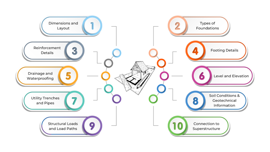
- Dimensions and Layout
The drawing should show the foundation’s overall shape, including walls, columns, and beams. It must have accurate measurements for proper alignment and spacing. It should also specify the depth and width of the foundation, depending on whether it is a slab, crawl space, or basement.
- Types of Foundations
The plan should clearly state the type of foundation being used, such as a concrete slab, pier, or crawl space. If special methods like deep foundations or piles are needed for unstable soil, these should also be included.
- Reinforcement Details
The drawing must include reinforcement details like the type, size, and spacing of steel bars (rebar) used in the foundation walls, footings, and slabs. Reinforcement helps the foundation handle the weight of the building.
- Footing Details
Footings support the foundation and spread the building’s weight evenly. The plan should show their size, depth, and shape, along with information on soil conditions and load-bearing capacity.
- Drainage and Waterproofing
To prevent water damage, the drawing should show drainage solutions like French drains, sump pumps, or waterproof coatings. Proper drainage ensures the foundation remains strong over time.
- Level and Elevation
Elevation markers should indicate the foundation’s height compared to the surrounding land. This ensures the foundation is level and prevents issues with water flow or uneven settling.
- Utility Trenches and Pipes
The plan must mark locations for utility lines such as water, gas, and electricity that pass through or under the foundation. This avoids conflicts during construction or future repairs.
- Soil Conditions and Geotechnical Information
The foundation design depends on soil conditions. The plan should reflect soil test results, including compaction, moisture levels, and load-bearing capacity, to ensure stability.
- Structural Loads and Load Paths
The drawing should show how the building’s weight is distributed across the foundation. It must specify different types of loads (live, dead, lateral) and how they are transferred to the ground.
- Connection to Superstructure
The plan should include how the foundation attaches to the rest of the building using anchor bolts, steel plates, or other connectors. This ensures the structure stays securely in place.
Adding all the important details helps construction teams avoid costly mistakes and ensures the foundation is built properly while following design and safety rules. However, to create an accurate foundation plan, you need a structured approach that guides construction teams and meets engineering standards.
Steps to Create a Foundation Plan Drawing

Creating a foundation plan drawing follows a step-by-step process to ensure the design is accurate, stable, and meets building standards. This drawing acts as a guide for engineers, architects, and contractors, showing the foundation’s layout, size, materials, and key structural details.
A well-planned foundation supports the building’s weight, fits the site conditions, and includes essential utilities. Below are the main steps to create a clear and detailed foundation drawing:
- Understand the Project Requirements
Consult with the architect or engineer to determine the foundation type—slab, strip, or piled. Assess site conditions like soil strength, groundwater levels, and climate, as these factors affect foundation design.
- Gather Necessary Information
Obtain architectural drawings, such as floor plans and elevations, to understand the building layout. A soil report helps determine foundation depth and reinforcement needs, while structural load calculations ensure the foundation can support both permanent and temporary loads.
- Select the Type of Foundation
Choose the foundation type based on soil conditions and structural needs. Shallow foundations, like slabs and strip footings, work when surface soil is strong.
Deep foundations, such as piles and caissons, are needed for weak surface soil. Special foundations, like raft or mat foundations, are also used for difficult soil conditions.
- Define the Dimensions
Set foundation depth based on soil conditions and determine footing width according to the building’s weight and soil capacity.
- Draw the Foundation Layout
Mark the locations of footings and walls to match architectural plans. Include drainage and waterproofing elements, like French drains or weeping tiles, to prevent water buildup.
- Include Reinforcement Details
Show reinforcement details, including placement, size, and spacing of rebar. In addition, include footing and slab reinforcement, such as wire mesh or steel bars, to support the structure.
- Add Foundation Sections and Elevations
Cross-sections illustrate foundation depth, footing placement, and structural elements like columns. Elevation views show foundation height in relation to the ground and building structure.
- Consider Utilities and Services
Plan for plumbing, electrical conduits, and insulation to ensure they don’t interfere with the foundation. Proper placement prevents structural issues.
- Include Soil and Site Details
Indicate soil bearing capacity and excavation requirements and include safety measures like bracing or shoring if needed.
- Specify Foundation Materials
Define concrete grade (e.g., M25 or M30) and any additional materials, such as reinforced masonry or stone.
- Review Building Codes and Regulations
Ensure compliance with local building codes and safety standards, especially for seismic or flood-prone areas.
- Finalise and Detail the Drawing
Ensure accuracy with proper scaling and clear labels for dimensions, materials, and reinforcements.
- Verify and Obtain Approvals
Get approval from a structural engineer and submit for local permit approval before construction begins.
- Hand Over to the Construction Team
Provide the finalised drawing to guide excavation and foundation work, ensuring proper execution of the design.
By following these steps, you can ensure a solid and reliable foundation for your building project. Understanding how to read and interpret foundation plan drawings is just as important as creating them.
Reading and Interpreting Foundation Plan Drawings
Reading and understanding foundation plan drawings is essential for engineers, architects, and construction teams. These drawings show the foundation’s layout, dimensions, reinforcement details, and load-bearing elements.
By studying the plan carefully, professionals can ensure the foundation is built correctly, following the design, structural needs, and safety rules.
Proper interpretation helps avoid mistakes, speeds up construction, and ensures that all key elements, such as footings, drainage, and utility connections, are placed accurately on-site.
Below is a simple guide to understand foundation plan drawings:
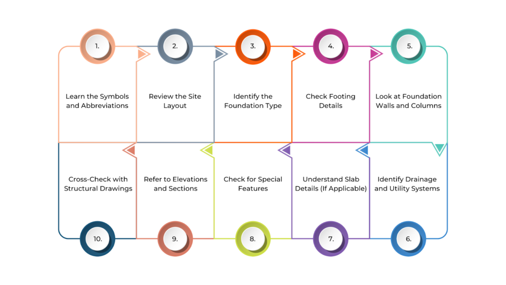
- Learn the Symbols and Abbreviations
Foundation plans use specific symbols and abbreviations to represent materials, structural elements, and construction details. Before interpreting the plan, check the legend or key that explains these symbols. Common ones include:
- Concrete symbols for slabs, footings, and walls
- Reinforcement symbols for rebar or steel bars
- Dimension marks showing distances and sizes
Knowing these symbols helps you understand the plan correctly.
- Review the Site Layout
The foundation plan usually starts with a site layout, showing property boundaries, existing buildings, and other features. Pay attention to:
- Building footprint: The outline of the building on the foundation
- Topography: Elevation or slope of the ground
- Setbacks and boundaries: The distance between the foundation and property lines, which may affect permits and zoning
- Identify the Foundation Type
The plan specifies the type of foundation based on soil conditions, building design, and regulations. Common types include:
- Slab-on-grade: A flat concrete slab resting on the ground
- Crawl space: A raised foundation allowing access to plumbing and utilities
- Full basement: A foundation extending below ground level, often used for extra space
- Pier and beam: Uses piers to support beams, ideal for unstable or freezing ground
Each type has specific details like slab thickness, footing depth, and number of piers.
- Check Footing Details
Footings distribute the building’s weight evenly across the soil, and the plan includes details such as footing dimensions for proper support, reinforcement placement for added strength, and the exact positioning of footings in relation to walls and columns.
- Look at Foundation Walls and Columns
Foundation walls provide vertical support, transferring the building’s weight to the foundation. The plan shows:
- Wall dimensions: Thickness, height, and materials (concrete, masonry, etc.)
- Reinforcement: Details on rebar placement for added strength
- Column placement: Positions and sizes of columns that support vertical loads
- Identify Drainage and Utility Systems
Proper drainage prevents water damage to the foundation. The plan may show pipes or drains directing water away from the structure or markings for water, sewer, and electrical lines running through the foundation.
- Understand Slab Details (If Applicable)
For slab foundations, the plan includes details such as slab thickness, which indicates the overall depth of the concrete and any variations in thickness for load-bearing areas. It also specifies rebar placement, detailing the size, spacing, and depth of reinforcement to ensure structural strength and durability.
- Check for Special Features
Some plans include extra details for durability and stability, such as:
- Expansion joints: Allow movement in large slabs due to temperature changes
- Anchor bolts: Secure the structure to the foundation
- Vapor barriers: Prevent moisture from seeping through the slab
- Refer to Elevations and Sections
Besides the top-down foundation plan, side-view drawings (elevations and sections) show depth, height, and other details that are not visible from above.
- Cross-Check with Structural Drawings
Structural drawings provide additional reinforcement details and measurements, ensuring the foundation is built correctly.
By understanding these elements, you can accurately interpret foundation plans, ensuring a strong and stable structure. If in doubt, consult an architect or engineer to avoid construction errors.
BIM Supports GREEN EARTH.

Conclusion
Foundation plan drawings are essential for the successful execution of any construction project. They provide a detailed guide for constructing a strong and stable foundation that supports the entire structure, ensuring safety, durability, and efficiency.
Accurate implementation of these plans requires strict adherence to regulations, effective coordination among all teams, and careful attention to detail. By prioritising these factors, construction teams can reduce errors, prevent delays, and improve safety, ultimately contributing to the smooth and timely completion of the project.
Are you looking for BIM solutions?
BIM ASSOCIATES is your one-stop BIM Solution provider for the Architecture and Structure discipline. Their solutions help clients with better decision-making, cost-saving, efficient construction planning, and green earth initiatives.
You might also like: SS, DD, and CD Drawings Explained for Successful Construction.
FAQs (Frequently Asked Questions)
1. What is the foundation drawing?
A foundation drawing is a detailed plan that guides the construction of a building’s foundation. It shows how to prepare the site, position footings, pour concrete, and install structural components.
2. What is the floor plan layout?
A floor plan is a scaled drawing that shows the arrangement of rooms, spaces, and pathways in a building from a top-down view. It helps visualise how different areas connect and function within a single level of the structure.
3. Who draws a foundation plan?
A structural engineer typically creates a foundation plan. They analyse the soil conditions and determine the best materials and design for the foundation to ensure it is strong and stable.