
General Arrangement (GA) Drawings are essential in design, construction, and engineering because they show how different parts fit together in a detailed layout. These drawings are used at every stage of a project, from planning to maintenance.
By providing a clear visual guide, GA drawings help teams work together, ensuring all components are placed and connected correctly. This reduces mistakes, improves communication, and keeps the project on track.
In this article, you’ll learn the various types of views in GA drawings, key notations and symbols, and the process of creating these detailed diagrams. In addition, you’ll explore how to interpret and read GA drawings, their practical applications in the construction industry, and the role of standardisation in ensuring clarity and consistency across projects.
What are General Arrangement Drawings?

General Arrangement (GA) Drawings are detailed technical drawings used in architecture, construction, engineering, and manufacturing. They show the overall layout of a layout, structure, system, or assembly.
These drawings include important details like dimensions, furniture, positions, and how components relate. GA drawings play a key role in project planning, coordination, and communication. They help ensure everything is correctly aligned before construction or manufacturing begins.
While GA drawings provide a complete overview of a structure or system, they are often compared to other types of technical drawings, such as location drawings.
Is a GA Drawing the Same as a Location Drawing?
In construction and architecture, you’ll often hear terms like GA drawings (General Arrangement drawings) and location drawings. They might seem similar, but they have different roles in the building process.
GA drawings give an overall layout of the architectural floor planview of a structure, showing how different parts fit together. On the other hand, location drawings focus on the exact placement of elements on-site. Knowing the difference between these two helps ensure accuracy in planning, coordination, and construction.
Below are the common differences between GA drawings and location drawings:
| Features | GA Drawings | Location Drawings |
| Purpose | Shows how different components fit together in a system or structure | Specifies the exact placement of elements within a site |
| Focus | Layout, spatial relationships, and orientations | Coordinates, elevations, and positioning details |
| Level of Detail | Medium – Provides an overview without installation specifics | High – Includes precise positioning and reference points |
| Use Case | Engineering, manufacturing, and construction planning | On-site installation and placement guidance |
| Content | Dimensions, section views, elevations, and component relationships. | Gridlines, reference points, elevations, and location coordinates |
| Audience | Engineers, designers, and planners | Contractors, installers, and site engineers |
| Examples | Floor plans, assembly layouts, equipment placement diagrams | Foundation layouts, gridline positioning, column locations |
Understanding how GA drawings differ from location drawings helps clarify their specific role in a project. Another key aspect of GA drawings is the way they represent structures through different views.
Different Types of Views in GA Drawings
General Arrangement (GA) drawings use different types of views, each giving a unique perspective of the building structure. These views help architects, engineers, and contractors understand the size, position, and details of each element, making it easier to plan and build accurately.
By combining these views, GA drawings ensure clarity, reduce errors, and improve coordination among teams. Below are the different types of views in GA drawings:
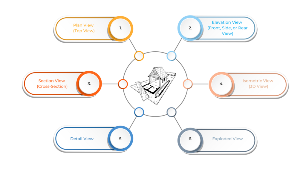
- Plan View (Top View)
This view represents the plan layout structure or spacial assembly as seen from above. It shows the layout of components, their dimensions, and spatial relationships. Plan views are commonly used in architectural, mechanical, and structural drawings to give a clear overview of how different elements are positioned.
- Elevation View (Front, Side, or Rear View)
This is a vertical representation of a building structure or component, displaying its height details and external features. Elevation views are useful for showing walls, facades, and other vertical elements, helping designers and builders understand how a structure will appear from different sides.
- Section View (Cross-Section)
This view provides an internal look at a building structure or component by cutting through it. It helps understand the internal arrangement, materials, and connections, making it useful for walls, piping systems, and machinery. Section views reveal details that may not be visible in other views.
- Isometric View (3D View)
This three-dimensional representation helps visualise how different elements fit together. It benefits complex form, structures and equipment layouts, providing a more realistic view of the assembly. Isometric views make it easier to interpret designs before construction or manufacturing begins.
- Detail View
This view focuses on a specific part of the drawing at a larger scale, showing intricate features, joints, and connections. It is used when a component requires additional clarification, ensuring that all fine details are properly understood for accurate execution.
- Exploded View
This view depicts components separated from one another to show the order of assembly. It helps understand how different parts fit together, making it common in mechanical and manufacturing drawings. Exploded views are invaluable in showing how to assemble or disassemble complex systems.
Each view serves a unique purpose, ensuring clarity and accuracy in construction and engineering projects. However, to fully understand GA drawings, it’s essential to recognise the usage of notations and symbols.
Also read: Detailed Drawings in Architectural Design: Types & Creation Process.
Notation and Symbols in GA Drawings
General Arrangement (GA) drawings use symbols and notations to show important information clearly. These standard symbols represent elements like walls, doors, and columns, helping design and construction teams stay consistent.
Notations provide extra details such as dimensions, materials, and reference points, making it easier to understand the drawings. Learning these symbols and annotations is key to reading GA drawings correctly and keeping the project on track.
Below are the notation and symbols used in GA drawings:
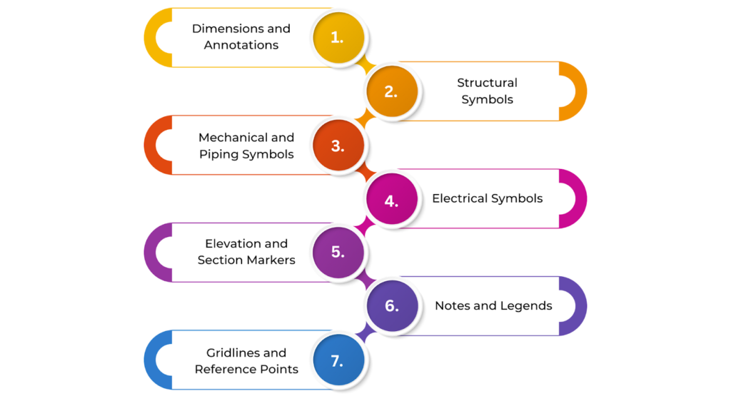
- Dimensions and Annotations
Linear dimensions represent the lengths, widths, and heights of different elements, while angular dimensions indicate angles between components. Leader lines and callouts connect specific elements to descriptions or instructions, making it easier to understand details. Tolerance notations define acceptable variations in size or shape, ensuring precision in construction.
- Structural Symbols
Columns are typically shown as filled or hatched rectangles or circles, while beams appear as parallel lines with size annotations. Walls are represented with thick lines for structural walls and thinner lines for partitions, helping to distinguish load-bearing elements from non-structural ones.
- Mechanical and Piping Symbols
Pipes and ducts are represented by lines of different thicknesses, with annotations specifying diameters. Valves, such as gate, ball, check, and butterfly valves, have distinct symbols for easy identification. Pumps and motors are commonly shown using circle-based symbols with labels for reference.
- Electrical Symbols
Switches and outlets have standardised symbols for power, lighting, and data connections. Wiring and conduits are represented by solid or dashed lines to indicate electrical routing. Panels and distribution boards are enclosed in boxed notations with labels to specify their functions.
- Elevation and Section Markers
Section lines indicate where a cross-sectional view is taken to show the internal details of a structure. Elevation arrows mark the direction from which a vertical view is shown, helping to clarify the height and appearance of different elements.
- Notes and Legends
General notes provide important information such as material specifications, safety instructions, and special installation guidelines. A legend key explains all the symbols and abbreviations used in the drawing, ensuring consistency and clear communication.
- Gridlines and Reference Points
Gridlines are labelled with numbers (for horizontal placement) and letters (for vertical placement) to help locate elements easily. Reference points indicate benchmarks or alignment guides, ensuring accurate positioning and coordination throughout the project.
Using notations and symbols in GA drawings improves efficiency, precision, and communication in any engineering or construction project. Creating GA drawings involves a structured process to ensure accuracy and clarity. From initial sketches to final digital models, each step contributes to a complete representation of the design.
Ready to simplify your projects and achieve the benefits?
BIM ASSOCIATES is your one-stop BIM Solution provider for Revit Architectural and Structural Solutions. They coordinate with your team to develop, record, and streamline the BIM Revit Model, along with the sheets, Bill of Quantities, Bill of Materials, and clash coordination.
The Creation Process of GA Drawings
Creating General Arrangement (GA) drawings is an important part of the design and construction process. These drawings give a clear overall view of a building or structure.
The process starts with gathering design inputs and setting drawing standards to ensure consistency. Specialised software is then used for precise drafting, making sure every detail is accurate. Each step helps improve clarity, accuracy, and coordination, ensuring the drawings meet project requirements.
To create GA drawings, follow these steps:
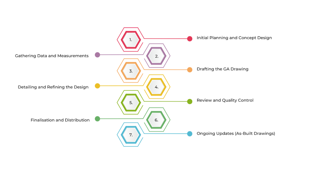
- Initial Planning and Concept Design
The process begins with setting project objectives, such as the intended use of the structure or system. Client requirements, including size, function, materials, and regulations, are gathered to ensure the design meets expectations.
A preliminary layout is then created to explore different design options, determining the basic arrangement and placement of components.
- Gathering Data and Measurements
If the project involves construction, a site survey is conducted to collect accurate measurements. For other projects, existing system details are documented. Component specifications, including dimensions, materials, and weight, are gathered.
Regulatory and compliance requirements, such as building codes and safety standards, are also reviewed to ensure the design meets all necessary guidelines.
- Drafting the GA Drawing
The appropriate views, such as plan, elevation, and section views, are chosen based on project complexity. Dimensions are carefully added to define the overall structure, internal components, and spacing.
Each component is positioned in the drawing according to the initial concept, ensuring proper alignment. Standardised symbols are used for columns, beams, and valves, while notations indicate dimensions, tolerances, and material specifications.
- Detailing and Refining the Design
Additional detailed views may be included to clarify intricate features like joints and connections. Section views are added to show internal arrangements, and exploded views may be included to show how different parts fit together for assembly. These refinements help improve clarity and accuracy.
- Review and Quality Control
The GA drawing is reviewed by project engineers, architects, or consultants to ensure accuracy and feasibility. Coordination with other disciplines, such as structural, electrical, and mechanical teams, ensures that all components integrate correctly. A final compliance check is conducted to verify that the drawing meets local codes and industry standards.
- Finalisation and Distribution
Based on feedback from the review process, necessary adjustments are made for clarity and compliance. Once finalised, the drawing is submitted for approval by the client or relevant stakeholders. The approved GA drawing is then distributed to construction teams, manufacturers, and contractors for execution.
- Ongoing Updates (As-Built Drawings)
Any modifications made during construction or assembly are recorded and updated in the GA drawings to reflect the actual built condition. Once the project is completed, the final version of the GA drawing is included in the project documentation for future reference and maintenance.
Creating a GA drawing is a collaborative process that involves a deep understanding of the project requirements and a systematic approach to ensure that all parts are aligned for successful execution. To make the most of GA drawings, it’s essential to understand how to read and interpret them correctly.
How to Read and Interpret GA Drawings?
General Arrangement (GA) drawings help visualise the layout and connections of different elements in a construction project. To read GA drawings effectively, you must understand symbols, notations, and different views, such as plan, elevation, and section views.
Knowing how to find and interpret the right information from these drawings ensures smooth planning, coordination, and project execution.

Below is a simple guide to understand how to read and interpret GA drawings:
- Understand the Types of Views
GA drawings use different views to represent a building layout structure. The Plan View (Top View) shows a bird’s-eye perspective, displaying component layouts and spacing. The Elevation View presents the front or side, showing heights and vertical arrangements.
The Section View cuts through the building, structure, revealing internal details and connections. The Isometric/3D View provides a three-dimensional perspective for better visualisation, while the Detail View zooms in on specific sections for clarity.
- Check the Drawing Title and Legend
The title of the drawing identifies the project, layout, structure, or system it represents, along with version details and revision numbers. The legend serves as a key, explaining symbols, abbreviations, and notations used in the drawing, ensuring accurate interpretation.
- Examine the Dimensions and Scale
Dimensions indicate lengths, widths, heights, depths, and spacing between components. They are marked directly on the drawing for precise measurements.
The scale, such as 1:100 or 1:50, determines how the drawing relates to real-world sizes, helping to interpret proportions accurately.
- Identify Key Components and Symbols
GA drawings use standard symbols to represent different elements. Columns, beams, and walls appear as thick lines or shapes, while pipes and ducts are depicted with various line styles and labelled diameters.
Electrical symbols indicate switches, outlets, and wiring, while mechanical parts like valves, pumps, and motors have unique symbols, all of which are explained in the legend.
- Look for Section and Elevation Markers
Section markers show where a cross-section has been taken to reveal internal arrangements. Elevation arrows indicate the direction of a vertical view, helping to understand how different elements appear from various angles.
- Review the Notes and Annotations
Notes provide extra information, such as material specifications, installation instructions, tolerances for permissible variations, and safety considerations like load-bearing details and construction warnings. These annotations help clarify construction requirements.
- Understand the Coordination with Other Systems
GA drawings often work alongside other technical drawings, like mechanical, electrical, and plumbing layouts. It’s important to check integration points where different systems connect and verify alignment to ensure everything fits within the overall design.
- Examine the Reference Marks and Gridlines
Gridlines act as a coordinate system, labelled with numbers (horizontal) and letters (vertical), making it easier to locate elements. Reference points mark benchmarks like the ground level or fixed datums, ensuring accurate placement during construction.
- Review Revisions and Updates
The revision history table shows any changes made to the drawing, including version updates. Revision clouds show specific areas that have been modified, ensuring that teams work with the latest version.
- Focus on the Overall Layout and Relationships
After analysing the details, step back and review the entire drawing. Assess how different systems integrate, ensuring smooth connections between mechanical, electrical, and structural components. Space planning should be checked to confirm that every element fits logically within the design.
Understanding how to read and interpret GA drawings is crucial for ensuring the accurate execution of construction projects. Once these drawings are properly analysed, they can be applied in various ways to simplify planning, coordination, and on-site operations.
Practical Applications of General Arrangement Drawings in the Construction Industry
General Arrangement (GA) drawings are essential in construction, acting as a visual blueprint for the entire building process. They provide a clear layout of structures, helping architects, engineers, and contractors work together smoothly. These drawings guide material placement, construction sequencing, and design coordination.
From the initial planning and approvals to on-site execution and quality control, GA drawings ensure accuracy, efficiency, and proper alignment across all teams involved in the project.
Below are some key practical applications of GA drawings in the construction industry:
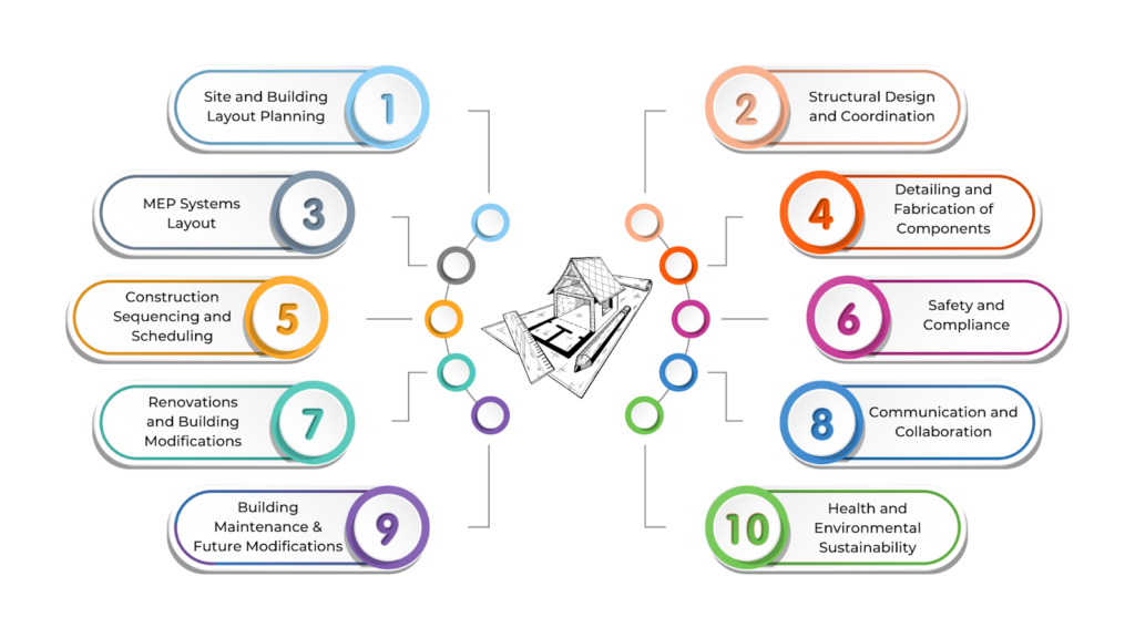
- Site and Building Layout Planning
GA drawings help determine the placement of the foundation, including columns, footings, and beams, ensuring proper alignment with structural elements. They also provide layouts for external site development, such as roads, parking areas, utilities, and drainage systems.
Additionally, these drawings assist in positioning the building accurately, considering setbacks, zoning regulations, and surrounding structures.
- Structural Design and Coordination
These drawings define the placement of load-bearing structures like columns, beams, walls, and floors, ensuring they meet safety requirements. They help coordinate different structural systems, such as steel framing, concrete, and masonry, providing seamless integration.
GA drawings also show how mechanical, electrical, and plumbing (MEP) systems fit within the structure to prevent clashes.
- MEPF (Mechanical, Electrical, Plumbing, Fire) Systems Layout
The HVAC system layout is detailed in GA drawings, specifying duct placements and ventilation points. They also show plumbing layouts, including water supply, drainage, and sewage lines, ensuring compatibility with other building elements.
Electrical layouts, including wiring, switchboards, and power distribution points, are also clearly marked to ensure safety and functionality.
- Detailing and Fabrication of Components
GA drawings provide exact dimensions, shapes, and specifications for various building components, ensuring accurate fabrication. They outline prefabricated elements, such as steel beams or concrete panels, that are constructed off-site and assembled on-site.
Additionally, they specify the materials for different structural components to ensure durability and compliance.
- Construction Sequencing and Scheduling
These drawings guide construction phasing, helping contractors plan excavation and finishing activities. They also indicate temporary supports, scaffolding, or bracing required during construction.
By providing clear views of different systems, GA drawings help coordinate trades like structural, electrical, and plumbing teams, minimising conflicts and delays.
- Safety and Compliance
Fire safety measures, including fire exits, stairways, and suppression systems, are clearly marked in GA drawings to ensure compliance with fire regulations.
Accessibility features like ramps, corridors, and doors are planned according to the regulations. GA drawings also verify compliance with local building codes regarding structural integrity and safety measures.
- Renovations and Building Modifications
As-built GA drawings document the existing structure, making future renovations easier. When expanding or upgrading buildings, these drawings help integrate new elements with the existing structure.
They also guide modifications by showing how current systems and layouts can accommodate changes.
- Communication and Collaboration
GA drawings serve as a common reference for architects, engineers, contractors, and clients, helping them visualise and approve designs.
They enhance project coordination by providing a clear overview of the structure, ensuring that different teams work together efficiently.
- Building Maintenance and Future Modifications
Facility managers use GA drawings to locate and maintain critical systems, such as HVAC, plumbing, and electrical components. They also assist in planning future upgrades, ensuring new additions align with the existing building structure.
- Health and Environmental Sustainability
These drawings support sustainability by integrating features like solar panels, energy-efficient HVAC systems, and rainwater harvesting solutions. They also help plan drainage, waste management, and energy-efficient building systems to reduce environmental impact.
By providing a clear and structured overview of the entire project, GA drawings ensure efficient planning, execution, and long-term maintenance of buildings. Consistency and clarity are key to making GA drawings effective across different projects and teams.
To achieve this, industry standards establish uniform guidelines for symbols, notations, and presentation, ensuring that GA drawings are easily understood and widely applicable.
Standardisation in GA Drawings
Standardisation in GA drawings is essential to keep construction plans clear, consistent, and accurate. By following well-known industry standards, these drawings use the same symbols, notations, and layouts across projects. This makes it easy for architects, engineers, and contractors to read and understand the drawings, reducing mistakes and confusion.
Standardisation also helps different teams work together smoothly, improving coordination and making the construction process more efficient. To maintain consistency in GA drawings, industry standards provide clear guidelines on presentation, notation, and layout. One such important standard is BS EN ISO 7519:1997.
Role of Standards like BS EN ISO 7519:1997
BS EN ISO 7519:1997 is an important standard that provides clear guidelines on creating construction drawings, including GA (General Arrangement) and assembly drawings. It explains how to present information, use symbols and notations, and set dimensions correctly.
Following this standard makes GA drawings clear and easy to understand for everyone involved, regardless of their location or background. Clear and uniform presentation in GA drawings is key to ensuring that all professionals involved in a project can quickly understand and interpret the information.
Maintaining consistency in symbols, notations, and layouts reduces confusion and improves collaboration across disciplines.
Importance of Consistent Presentation and Clarity
Standardising GA drawings makes them easier to understand and ensures clarity across different projects and companies. Without a common standard, symbols, notations, and terminology may vary, leading to confusion. By following industry standards, everyone—architects, engineers, builders, and maintenance teams—can interpret drawings correctly and work in sync.
This is especially important in the digital age, where CAD and BIM software are widely used. Standardisation helps ensure that GA drawings remain compatible across different software platforms and devices, making collaboration smoother and reducing errors.
BIM Supports GREEN EARTH.

Conclusion
General Arrangement (GA) Drawings play a key role in every stage of a building’s life—design, construction, and maintenance. They provide clear and detailed layouts to ensure accuracy and coordination.
With the help of modern technologies like 3D modelling, CAD, and BIM, GA drawings have become even more precise, allowing teams to spot issues early and work more efficiently.
These drawings serve as reliable guides during construction, maintenance, and future upgrades, making them essential throughout a building’s lifecycle.
Are you looking for BIM solutions?
BIM ASSOCIATES is your one-stop BIM Solution provider for the Architecture and Structure discipline. Their solutions help clients with better decision-making, cost-saving, efficient construction planning, and green earth initiatives.
You might also like: Section Drawings in Architecture: Key Elements, Types, & Best Practices.
FAQs (Frequently Asked Questions)
1. What is a GA drawing?
A General Arrangement (GA) drawing shows the overall layout of a structure, such as a building. Unlike detailed component or assembly drawings that focus on specific parts, GA drawings provide a complete view of how different elements fit together in the design.
2. What are the requirements for general arrangement drawings?
GA drawings should include enough details to show key elements like process equipment, material storage, power distribution, utilities, floor levels, column placements, access points, stair locations, and the overall shape of the structure.
3. What is the difference between GA and layout drawing?
GA drawings focus on specific equipment areas and provide detailed information on support locations and types, making them useful for on-site fabrication work. In contrast, layout drawings cover a broader view of the project, showing the general positioning of different elements within a space.