Research says that design changes in the construction industry contribute to 56.5% of cost overruns and 40% of project delays, often due to miscommunication or incomplete planning. This is where construction drawings play a crucial role, providing a structured framework to keep projects on track.
These detailed diagrams provide a clear blueprint of the design, materials, and measurements, keeping architects, engineers, and contractors aligned. They minimise errors, reduce modifications, and help control costs and delays.
This article shares the importance of construction drawings, their types, key components, and their role in regulatory and contractual compliance.
Overview of Building Drawings
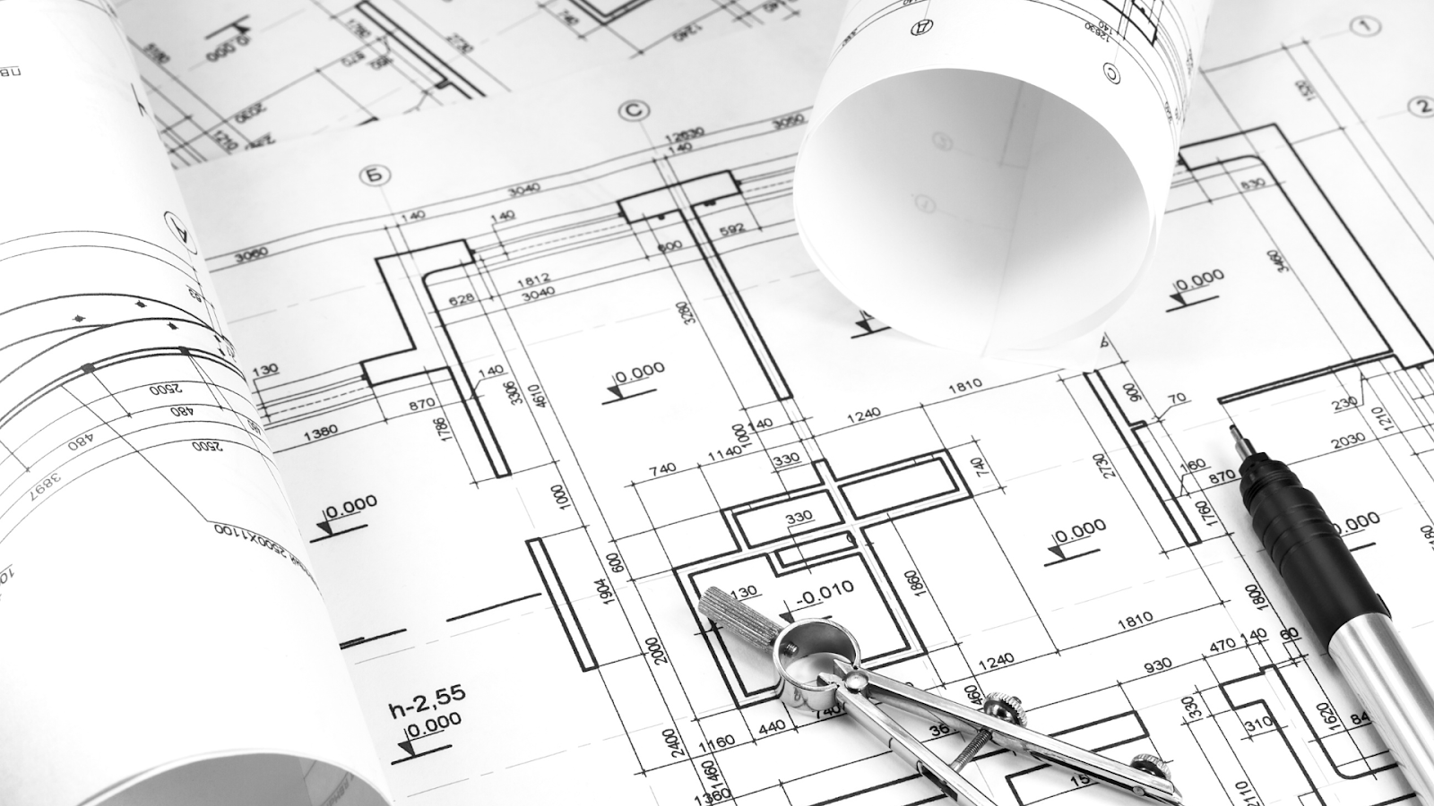
Building drawings are the starting point of any construction project. They show a clear picture of the structure before work begins and include essential design and technical details that help architects, engineers, contractors, & clients understand and agree on the project plan.
Drawings are used in building design for many purposes, such as:
- Visualising the Design Concept: Drawings turn ideas into clear pictures, showing how the building will look before construction starts. This helps everyone make better decisions and ensures they understand the design similarly.
- Ensuring Accuracy and Precision: Detailed drawings provide exact measurements, materials, and construction methods, helping prevent costly mistakes, confusion, and structural problems.
- Facilitating Communication Among Stakeholders: Many experts, like architects, engineers, and contractors, work on a building project. Drawings act as a common language, making it easier for them to communicate and avoid misunderstandings.
- Compliance with Regulations and Standards: Architectural and engineering drawings ensure the design follows local laws, safety rules, and environmental guidelines. Authorities check and approve these drawings before permitting them to start construction.
- Structural Planning and Safety: Structural drawings show the building’s framework, including load-bearing parts, foundation details, and reinforcement. These details ensure the building’s strength, stability, and safety.
- Cost Estimation and Budget Planning: Detailed drawings provide exact measurements, helping project managers calculate material needs, labour costs, & the total budget. This helps in proper financial planning and efficient use of resources.
- Coordination of Different Building Systems: Modern buildings include electrical wiring, plumbing, heating, cooling, and fire safety systems. Drawings help ensure these systems fit together properly without conflicts and make the best use of space.
- Serving as Legal and Contractual Documents: Approved drawings define project details, work requirements, and agreements between parties. If there is a dispute, these drawings serve as proof to help resolve issues.
- Supporting Future Maintenance and Modifications: Once construction is completed, as-built drawings are used for renovations, repairs, and maintenance. They provide a clear record of the building’s structure and systems.
Building drawings provide a structured visual representation of a construction project, detailing everything from layout to materials and compliance requirements. Preparing these drawings requires careful planning, precise measurements, and adherence to design and regulatory standards.
How are Building Drawings Prepared?
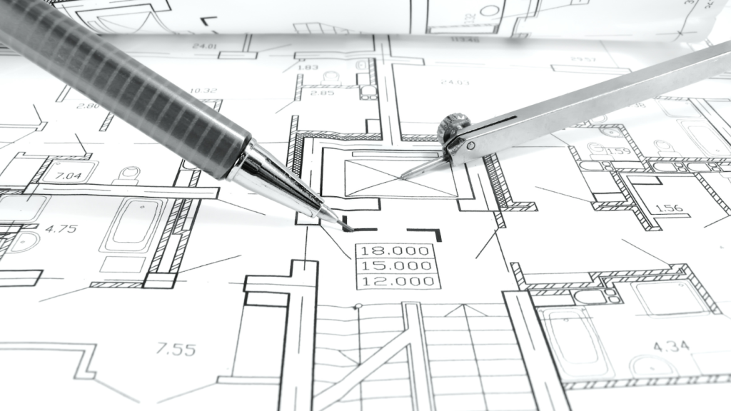
Building drawings are created through a structured process that includes conceptualisation, design, and technical detailing. Architects and engineers begin by gathering project requirements, assessing site conditions, and ensuring compliance with regulations.
Initial sketches are then refined into precise architectural drawings, such as floor plans, general arrangement plans, Shop drawings, elevations, and sections, using CAD software. Structural engineers design the foundation and framing plans, while MEPF specialists develop layouts for mechanical, electrical, and plumbing systems.
The drawings are carefully reviewed for accuracy, regulatory compliance, & construction feasibility. Once approved, they become the official blueprint for the project, ensuring precise execution and smooth coordination among all disciplines.
Creating precise and well-structured design drawings requires expertise from professionals across different disciplines.
Who Prepares Design Drawings?
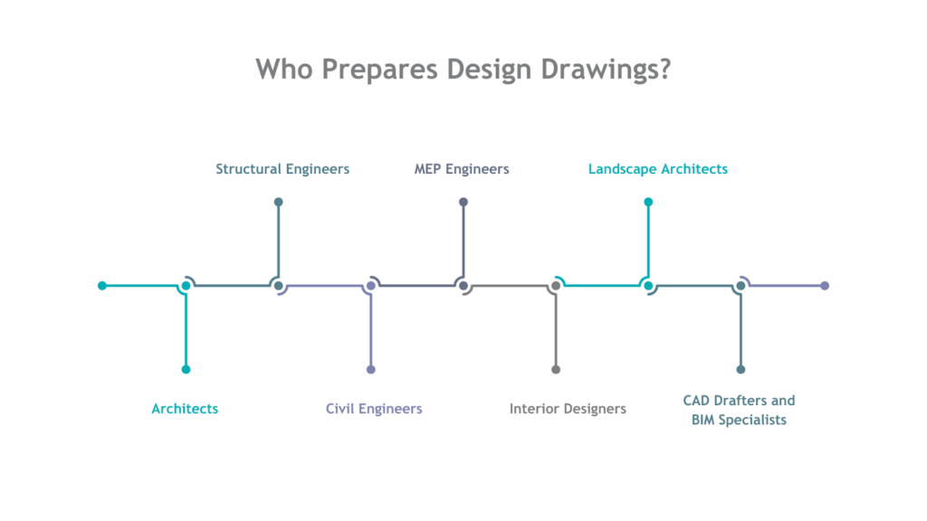
Design drawings are developed by a team of professionals. Each of the professionals specialises in different aspects of building design and construction. Their combined expertise ensures the structure is safe, functional, and meets all regulatory requirements.
Below is an overview of the professionals who prepare design drawings:
| Profession | Roles & Responsibilities |
| Architects | Lead the design process, ensuring the building’s aesthetics, function, general arrangement and compliance with local government regulations.Create key drawings like floor plans and elevations. |
| Structural Engineers | Design the building’s framework/structure to ensure stability.Create detailed plans for foundations, framing, and reinforcements as per loan and usage of the building.They also have to follow local government bylaws. |
| Civil Engineers | Plan the site layout, including grading, drainage, and infrastructure.Prepare drawings for roads and water systems.Also take care of building construction and quality check during construction process. |
| MEPF Engineers | Design the building’s mechanical, electrical, and plumbing systemCreates design for HVAC, wiring, and plumbing layouts. |
| Interior Designers | Plan and create layouts, furniture, material, arrangements, and lighting designs.Enhance the building’s functionality and appearance. |
| Landscape Architects | Design outdoor spaces, incorporating features like gardens and walkways.Soft landscape, hard landscape, Plantations according to soil type. Create eco-friendly landscape drawings. |
| CAD Drafters and BIM Specialists | Convert sketches into digital plans with standardsEnsure accurate, coordinated designs using CAD & BIM software and BIM standards |
Each professional plays a key role in creating design drawings, ensuring the building is functional, safe, and meets all project requirements. Once the design is finalised, it gets converted into detailed construction drawings.
Also read: SD, DD, and CD Drawings Explained for Successful Construction.
What are Construction Drawings, and Why are They Important?
Construction drawings are detailed documents that provide clear instructions for building a structure. They connect the design and actual construction, showing dimensions, materials, structural parts, and installation details.
These drawings help architects, engineers, contractors, and builders follow the design accurately and make sure everything meets safety and building codes.
Construction drawings are essential for many reasons, such as:
- Guiding Construction: Providing a clear roadmap for contractors and workers, ensuring precise implementation.
- Preventing Miscommunication: Acting as a common reference for architects, engineers, and builders, avoiding misinterpretations.
- Planning and Budgeting: Assisting in planning for material purchases and budgeting based on the project details.
- Coordinating Designs: Ensuring that architectural, structural, and MEPF designs work together to prevent issues during construction.
- Legal and Contractual Reference: Acting as official documents to resolve disputes, claims, or changes during the project.
- Avoiding Errors and Waste: Reducing errors, minimising material wastage, and preventing costly rework.
- Compliance: Ensuring adherence to building codes, safety regulations, and zoning laws.
Construction drawings form the foundation of a successful project, ensuring clarity, accuracy, and compliance at every stage. Each type of drawing serves a specific purpose, covering all aspects of construction in detail.
Looking to improve precision and simplify your workflow?
BIM ASSOCIATES is your one-stop BIM Solution provider for Revit Architectural and Structural Solutions. They coordinate with your team to develop, record, and streamline the BIM Revit Model, along with the sheets, Bill of Quantities, Bill of Materials, and clash coordination.
Types of Construction Drawings & Key Details to Include
There are various types of construction drawings, each with a specific role during the process. Understanding the types of construction drawings is key to ensuring the project is carried out successfully, from design to completion.
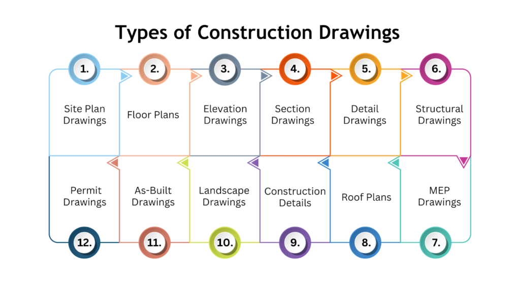
Below is an overview of the different types of construction drawings:
1. Site Plan Drawings
Site plans show the layout of the entire project on the construction site, including boundaries, roads, utilities, and landscaping. They provide a top-down view of the building and often include details like its orientation, parking areas, walkways, and nearby features. The key details include:
- Boundaries, roads, and walkways.
- Location of utilities (water, gas, etc.).
- Topography (contours and slopes).
- Site features like trees, bodies of water, and nearby structures.
- Zoning and legal restrictions.
- Access routes for construction equipment and vehicles.
- Demolition or existing conditions (if applicable).
2. Floor Plans
Floor plans are detailed drawings that show the layout of rooms, walls, doors, windows, and other parts of the building on each floor. They help builders understand the interior arrangement of the building. The key details include:
- Names of rooms and their uses.
- Scale and dimensions.
- Size and construction details of external and internal walls (may include a key/legend for materials).
- Location of structural elements like beams, columns, and lintels.
- Stair locations and directions.
- References to section lines and detail drawings.
- Material details, specifications, and notes.
- Heating, ventilation, and air conditioning (HVAC) layout (sometimes shown in a separate drawing).
- Electrical system layout (sometimes a separate drawing).
- Water and drainage system layout.
- Fire safety provisions (emergency exits, alarms, etc.).
- Building levels (e.g., finished floor level, ground level).
3. Elevation Drawings
Elevations are views of the building’s exterior, showing what it will look like from different sides. They include details about the height, materials, placement of windows and doors, and overall appearance. The key details include:
- Exterior views of the building from all sides.
- Height and scale of the building.
- Window, door, and other opening locations.
- Building material and finish details.
- Rooflines and parapet details.
- External features like balconies, chimneys, and facades.
- Decorative elements and architectural details.
- Height measurements (finished floor level to finished ceiling level)
4. Section Drawings
Sections are cut-through views of the building, showing the internal structure as if it had been sliced. These drawings help explain how different building levels connect, including ceiling heights, floor thicknesses, and the placement of plumbing or electrical systems. The key details include:
- Vertical cuts through the building, showing the relationship between floors.
- Internal components (walls, floors, ceilings, and roofs).
- Structural elements (e.g., beams, foundations).
- Room heights, ceiling levels, and floor slopes.
- Key dimensions (floor-to-floor height, structural elements).
- Staircase details, ramps, and other vertical circulation.
5. Detail Drawings
Detail drawings focus on specific construction parts, like door frames, staircases, or joints. They provide a closer look at these components, showing exact measurements and specifications to ensure everything is built accurately. The key details include:
Close-up views of specific construction details (e.g., window installation, door frames).
- Detailed material specifications.
- Jointing methods and fasteners.
- Construction connections and transitions.
- Any unique or complex features of the building.
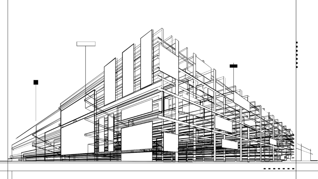
6. Structural Drawings
Structural drawings show the building’s framework and support systems, such as foundations, columns, beams, and load-bearing walls. Structural engineers usually create them to ensure the building’s stability and safety. The key details include:
- Location and details of structural elements (e.g., foundations, beams, columns, slabs).
- Load-bearing capacity.
- Material specifications for structural components.
- Connection details between structural elements.
- Reinforcement details (e.g., steel rebar in concrete).
- Structural elements’ dimensions and material types.
7. Mechanical, Electrical, and Plumbing, Fire (MEPF) Drawings
MEP drawings show the layout and installation details for mechanical systems (like heating and cooling), electrical systems (such as wiring and lighting), and plumbing systems (pipes and fixtures). These drawings ensure these systems are properly set up and work well with the rest of the building. The key details include:
- Mechanical systems layout (heating, ventilation, and air conditioning – HVAC).
- Electrical wiring, outlets, switches, lighting, and panel locations.
- Plumbing systems for water supply, drainage, and sewage.
- Location of air handling units, ductwork, and vents.
- Fire alarm and sprinkler systems.
- Compliance with building codes and energy standards.
8. Roof Plans
Roof plans show the layout and details of the roof, including its slopes, drainage systems, and materials. These drawings help you understand how the roof is built and how it fits with the rest of the building. The key details include:
- Roof layout and slope details.
- Drainage systems (gutters, downspouts, drains).
- Materials used for roofing.
- Locations of roof penetrations (e.g., vents, skylights, chimneys).
- Roof structure and support systems (rafters, trusses).
- Waterproofing and insulation details.
9. Construction Details
These drawings provide specific instructions for building certain construction parts, such as installing a window or creating a wall. They also include information about materials, methods, and connections. The key details include:
- Specific construction components like staircases, window and door frames, wall junctions, etc.
- Key measurements and material notes.
- Construction techniques or special requirements for certain elements.
- Any unique architectural or structural features that require special attention.
10. Landscape Drawings
Landscape plans show the layout of outdoor spaces, like gardens, lawns, patios, and paths. They often include details about plants, irrigation systems, outdoor lighting, and other elements that make up the exterior design of the building. The key details include:
- Outdoor features such as planting areas, paths, and recreational spaces.
- Location of trees, shrubs, and other vegetation.
- Hardscaping (e.g., patios, retaining walls, fences).
- Site drainage and water management (e.g., ponds, stormwater systems).
- Lighting and other outdoor electrical components.
- Irrigation system layout.
11. As-Built Drawings
As-built drawings show what the building looks like once it’s finished, including any changes made during construction. They are important for future repairs or updates, accurately recording the final structure for maintenance, legal requirements, and managing the building. The key details include:
- Final layout and construction details after the project is completed.
- Any deviations or changes from the original design.
- Location and installation of any added systems or components.
- Measurements and details based on the actual built condition.
12. Permit Drawings
Permit drawings are the official plans submitted to the local government or other authorities to get permission for construction. These drawings meet specific rules and regulations to ensure the building follows zoning laws, safety codes, and other requirements. The key details include:
- Drawings are required by local authorities to obtain permits.
- Compliance with zoning laws, building codes, and regulations.
- Structural, fire, and life safety considerations.
- Detailed site plans, floor plans, and elevations for approval.
- Specific notes and requirements for inspections and approvals.
Each of these drawings has a specific purpose in the construction process, ensuring the project runs smoothly & as planned. They also help different professionals involved in the project communicate clearly, reducing errors and misunderstandings.
Besides showing technical details, construction drawings must also follow building rules and contract requirements. They help ensure the project meets safety standards, legal agreements, and design specifications.
Regulatory and Contractual Drawings
Regulatory and contractual drawings are important documents that ensure a construction project follows legal rules and meets contract terms.
Regulatory drawings are made to comply with local authorities’ rules, building codes, and safety standards. They ensure the project follows zoning laws, safety regulations, and environmental guidelines. Regulatory drawings are usually part of the permit application and must be reviewed and approved by the authorities before construction can start.
On the other hand, contractual drawings are part of the official contract between the project owner and the contractor. They outline the work to be done, the materials to be used, and the quality expected. Contractual drawings help both sides avoid misunderstandings and ensure the project is completed as agreed. They include timelines, budgets, and specific material and work requirements.
Regulatory and contractual drawings work together to ensure the project meets legal, safety, and contract requirements, helping avoid problems during construction. BIM Supports GREEN EARTH.

Conclusion
Construction drawings are crucial for accuracy, efficiency, and compliance in any project. They act like a roadmap, guiding every stage from design to completion, ensuring smooth execution.
These drawings keep all stakeholders—designers, contractors, and regulatory bodies—aligned, helping projects stay on track and meet legal and safety standards. Without them, achieving precision and efficiency in construction would be nearly impossible.
By understanding and using different types of construction drawings effectively, you can simplify project execution, prevent costly mistakes, and build with confidence.
Are you looking for BIM solutions?
BIM ASSOCIATES is your one-stop BIM Solution provider for the Architecture and Structure discipline. Their solutions help clients with better decision-making, cost-saving, efficient construction planning, and green earth initiatives.
You might also like: How Does BIM Help Construction Teams Improve Efficiency and Accuracy?
FAQs (Frequently Asked Questions)
1. What is a drawing of a building?
Construction drawings are visual plans that show the layout, parts, structure, and size of a building or construction project. These drawings act as a guide for building the project.
2. Who designs construction drawings?
Architects, engineers, quantity surveyors, interior designers, or anyone who designs and changes building plans can create construction drawings.
3. What is the floor plan layout?
A floor plan is a drawing that shows the layout of a building’s rooms, spaces, and features from above. It helps show how rooms are connected, how people move around, and how the building is arranged on one level.