Research shows that design changes in the construction industry are a leading cause of cost overruns, often due to miscommunication or incomplete planning. This is where section drawings play a crucial role, providing a detailed, internal view of a building’s structure and layout.
These drawings are essential for understanding how various elements, such as walls, floors, materials, and structural components, interact and work together, ensuring that the building’s design is both functional and structurally sound.
By clearly showing how the building’s parts relate to each other, section drawings help identify potential design flaws and construction issues early on, preventing costly mistakes later in the process.
This article shares the importance of section drawings in architecture, their key elements, various types and styles, and practical tips on how to read, create, and improve them to enhance design clarity and construction accuracy.
Understanding Section Drawings in Architecture
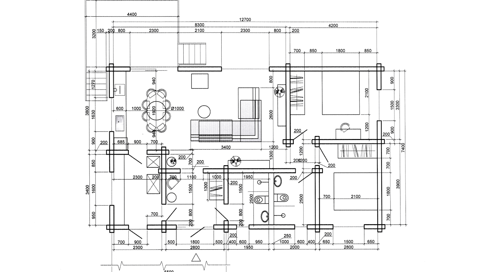
Section drawings in architecture are detailed representations that show what a building looks like on the inside as if it’s been sliced open along an imaginary line. This “cut” gives you a clear view of the internal layout, materials, and how different building parts fit together.
These drawings are invaluable to architects, engineers, and builders throughout the design and construction stages. They help connect design ideas to the construction process, ensuring everyone is aligned and follows the design plan accurately.
Section drawings provide a detailed view of a building’s architecture, structure and furniture layout, joints, materials, allowing professionals to see what lies beneath the surface.
What Does a Section Drawing Show?
A section drawing offers a clear, cut-through view of important features like walls, floors, ceilings, roofs, staircases, windows, and doors. It also reveals the materials used, their thickness, and how different parts are connected to ensure the building’s strength and stability.
The section also includes vertical measurements, such as the height of floors and ceilings, and shows how different building levels are connected. Sometimes, it contains notes, labels, and construction details to guide builders in following the design accurately.
A good section drawing also includes details about the surrounding site to show how the building fits into its environment. For example, it can be difficult to see the thickness of a floor slab in an elevation or the empty spaces in a floor plan, but a section drawing clearly shows these details.
Similarly, while contour lines on a site plan can show sloping land, a section drawing makes it easier to understand the steepness of the terrain.
Section drawings not only clarify a building’s internal details but also reveal how it interacts with its environment. They provide a deeper level of understanding that other drawing types, like plans and elevations, might not fully capture.
Difference Between Section, Plan, and Elevation Drawings
In architectural design, section, plan, and elevation drawings are three key types of technical drawings that show different views of a building. Each one provides a unique perspective that helps you understand the structure’s layout, purpose, and appearance.
The main difference between these drawings lies in the type of information they convey: plans show horizontal layouts, sections depict vertical cuts through the building to reveal internal details, and elevations provide exterior views, focusing on the building’s appearance and facade.
Below are the key differences between section drawings, plan drawings, and elevation drawings:
| Aspects | Section Drawings | Plan Drawings | Elevation Drawings |
| Definition | A vertical or horizontal cut-through view of a building’s interior. | A top-down view of a building that shows the layout from above. | A flat, vertical view of a building’s exterior or interior walls. |
| Viewpoint | Cross-sectional view (as if the building is sliced). | Bird’s-eye view (from above). | Front-on or side-on view (looking straight at a facade or wall). |
| Purpose | To reveal the internal structure, material layers, and spatial relationships. | To show room layouts, furniture placement, door swings, and circulation patterns. | To display the appearance, height, and design of walls, windows, and doors. |
| Focus | Vertical relationships, construction details, and internal components. | Horizontal layout and space distribution. | External design, facade treatments, and wall detailing. |
| Key Elements | Structural elements like walls, floors, ceilings, staircases, and materials. | Walls, windows, doors, furniture, and circulation paths. | Wall elevations, window placements, decorative features, and exterior finishes. |
| Line Weight | Cut elements in bold and background elements in lighter lines. | Thicker lines for walls, thinner lines for fixtures and fittings. | Uniform line weights for surfaces; thicker for closer objects. |
| Annotations | Material hatching, dimensions, floor levels, and structural notes. | Room names, dimensions, door/window symbols, and furniture labels. | Elevation heights, materials, window/door sizes, and decorative details. |
| Orientation | Vertical or horizontal cut through the structure. | Horizontal section cut, typically 1m above the floor. | Vertical view, showing the face of the building. |
| Use in Construction | Essential for understanding construction methods, materials, and structural details. | Helps in planning space usage, furniture layout, and circulation. | Used for exterior detailing, facade design, and window/door placement. |
| Examples | Building sections, wall sections, detail sections. | Floor plans, roof plans, and site plans. | Front, rear, and side elevations; interior elevations. |
Understanding the differences between section, plan, and elevation drawings highlights how each represents a building’s design in a unique way. Section drawings stand out because they offer a clear view of a building’s internal structure.
Importance of Section Drawings in Architecture
Section drawings are vital to architectural design as they fill the gap between design concepts and real-world construction by clearly communicating spatial relationships, material choices, and the building’s structural integrity.
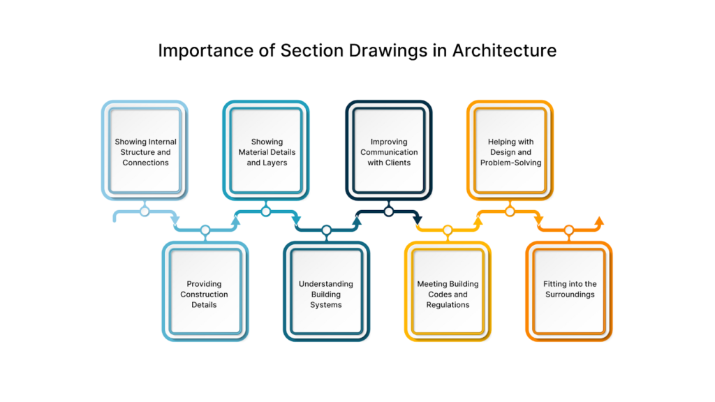
These drawings are especially important for showing complex systems, layers of materials, and vertical elements. In architecture, section drawings play a crucial role in bringing the design to life by:
Showing Internal Structure and Connections
Section drawings clearly show how different building parts, like floors, walls, and structural elements, connect. They help designers plan spaces efficiently by showing how areas are linked vertically and horizontally.
Features like staircases, mezzanines, and double-height spaces, which are hard to understand in regular plans or elevations, are easy to see in sections.
Providing Construction Details
Builders use section drawings to understand the technical parts of a building. These drawings show wall layers, including insulation, cladding, and structural components.
They also explain how parts connect, like where a floor meets a wall or how a roof is supported. This detail reduces mistakes and ensures the building is constructed correctly.
Section drawings use patterns and labels to show the materials used in walls, floors, and roofs. This helps builders know what materials to use and where to place them, ensuring the design meets regulations and standards.
Understanding Building Systems
Modern buildings have systems like HVAC, plumbing, and electrical wiring, and section drawings show how these systems run through walls, ceilings, and floors. This helps engineers plan and avoid issues during construction by coordinating everything properly.
Improving Communication with Clients
Section drawings help clients understand how a building will look and feel. They show details like room heights, window placements, and space sizes, making communication easier between clients and designers.
Meeting Building Codes and Regulations
Architects use section drawings to show that a building follows rules for safety, strength, accessibility, and energy efficiency. For example, sections can highlight proper insulation, stair sizes, and designs for easy access.
Helping with Design and Problem-Solving
Section drawings helps architects explore different layouts, materials, and structural ideas during design. They show how light enters rooms, air flows, and building parts work together, allowing designers to improve their plans.
Fitting into the Surroundings
Site sections shows how a building fits into its landscape, nearby buildings, and terrain. This is especially useful for buildings on slopes or in areas with unique environmental or design needs. It shows how the building fits with the surrounding land and how its parts align with natural features and nearby structures.
To understand a section drawing nicely, it’s important to put emphasis on the key details that bring it to life and ensure the design is accurate.
Also read: SD, DD, and CD Drawings Explained for Successful Construction.
Key Elements of Section Drawings
Section drawings capture the internal details of a building, providing a clear representation of how different components function within the space. To effectively communicate the design, these drawings rely on key elements that define the structure, materials, and dimensions.
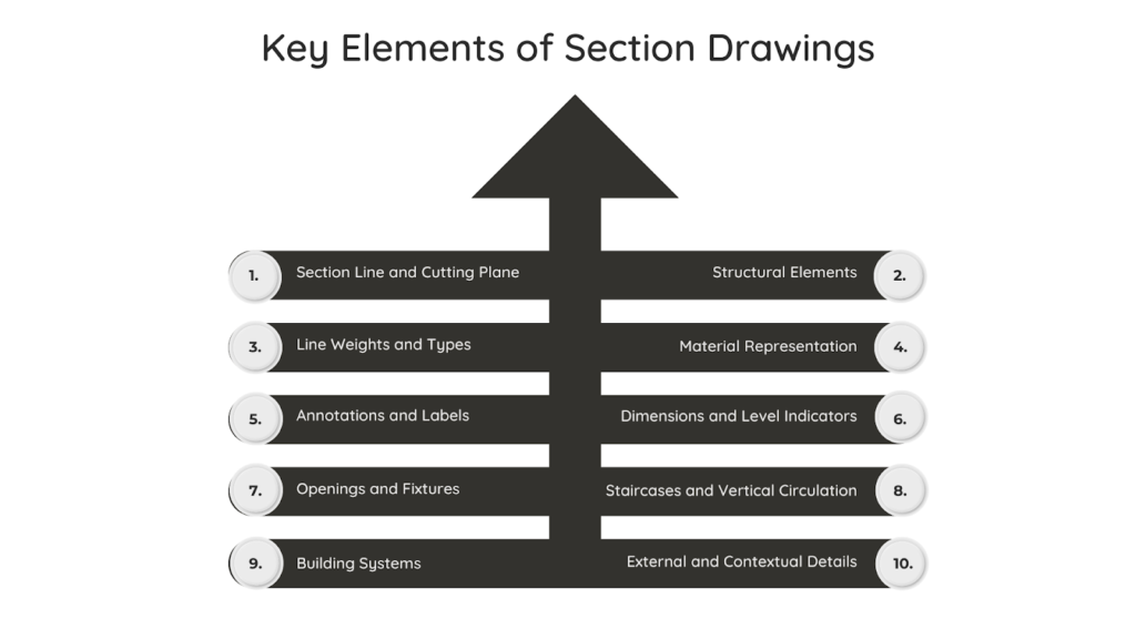
Each of these elements plays an important role in making the drawing clear, informative, and useful for both design and construction. The key elements of section drawings include:
1. Section Line and Cutting Plane
The section line is found on the floor plan and shows where the building is “cut” to create the section view. It’s usually marked with arrows pointing toward the section view, like A-A or B-B.
On the other hand, the cutting plane is the imaginary line where the cut happens. This plane is usually vertical but can also be horizontal, depending on what needs to be shown.
2. Structural Elements
Section drawings show the layers and parts of a building in detail. They provide precise information about how structural components come together and interact within the design, such as:
- Walls: Shown with bold, solid lines where the cut is made, displaying their thickness and materials.
- Floors and Ceilings: Highlight floor slabs, ceiling finishes, and hanging ceiling elements.
- Columns and Beams: Show vertical supports (columns) and horizontal structures (beams) with their size and material details.
3. Line Weights and Types
Line weights are essential for making section drawings easy to understand. They help distinguish between various elements, ensuring clarity and effective communication of design intent.
Different line types and weights are used in section drawings to clearly distinguish between visible and hidden elements, such as:
- Bold Lines: Show parts cut by the section plane, like walls and floors.
- Lighter Lines: Show parts beyond the cut, like windows or furniture.
- Dashed Lines: Indicate hidden or overhead features, like ceiling beams.
4. Material Representation (Hatching)
Section drawings use hatch patterns to represent different materials, helping builders recognise and understand their use in the structure. These patterns provide a quick and effective way to communicate construction details.
Each material in a section drawing is assigned a unique hatch pattern, making it easy to distinguish between them, such as:
- Brick: Typically depicted using diagonal lines to represent its texture and layering in construction.
- Concrete: Represented by a pattern of random dots or stippling to illustrate its solid and dense composition.
- Insulation: Shown with wavy or zigzag lines to indicate its soft and flexible material properties.
5. Annotations and Labels
Labels are used to identify key building elements such as walls, floors, and supports. They help clearly distinguish each part and make it easy to understand the layout and structure of the building.
Annotations, on the other hand, provide additional details such as materials, insulation, and construction instructions. Common symbols like “T.O.S.” (Top of Slab), “F.F.L.” (Finished Floor Level), and “W” (Window locations) help further clarify specific locations and elements in the design.
6. Dimensions and Level Indicators
Accurate measurements and levels are crucial in section drawings, ensuring that every element is constructed to the correct specifications and aligns properly with the rest of the building.
Clear and precise dimensions are essential for understanding the scale and positioning of components within the drawing. These include:
- Vertical Dimensions: Show the height of floors, ceiling levels, and roof slopes.
- Horizontal Dimensions: Show the distances between walls and structural parts.
- Elevation Markers: Refer to finished floor levels (FFL) and structural slab levels (SSL) compared to a fixed starting point.
7. Openings and Fixtures
Section drawings show windows, doors, and other openings as if they’ve been cut through, clearly revealing their inner parts. Window sections include details such as the height of the sill, lintel, glass, and frame.
For doors, the drawing highlights the door frame, bottom edge, thickness, and space around the door, ensuring that the opening is accurately represented and fits smoothly into the overall design.
8. Staircases and Vertical Circulation
Staircases are shown with section lines cutting through the steps, highlighting key details such as the height of the steps, depth of the treads, and location of the handrails. Arrows indicate the direction of movement, showing whether it’s going up or down.
9. Building Systems (MEP)
Mechanical, Electrical, and Plumbing (MEP) systems are often included in detailed section drawings. HVAC ducts, plumbing pipes, and electrical wires are represented using standard symbols, showing how these systems fit into walls, floors, and ceilings.
These section drawings facilitate the collaboration of architects, engineers, and contractors, reducing the chances of problems between systems.
For example, they help prevent issues where HVAC ducts and plumbing pipes might clash, saving both time and money during construction. MEP section drawings also help ensure the building meets codes by clearly showing required spaces, pipe slopes, and other important details.
10. External and Contextual Details
Sections can extend beyond the building to show the surrounding site. Site sections display ground levels, retaining walls, landscaping, and how the building interacts with nearby structures. They can also highlight natural light paths or airflow for ventilation.
By including these important details, section drawings become essential for communicating design ideas, addressing construction challenges, and ensuring a successful project.
Different types and styles of section drawings are important for showing these details, focusing on various aspects of the building’s design and structure.
Are you looking to improve precision and simplify your workflow?
BIM ASSOCIATES is your one-stop BIM Solution provider for Revit Architectural and Structural Solutions. They coordinate with your team to develop, record, and streamline the BIM Revit Model, along with the sheets, Bill of Quantities, Bill of Materials, and clash coordination.
Types of Sections Drawings and Section Styles
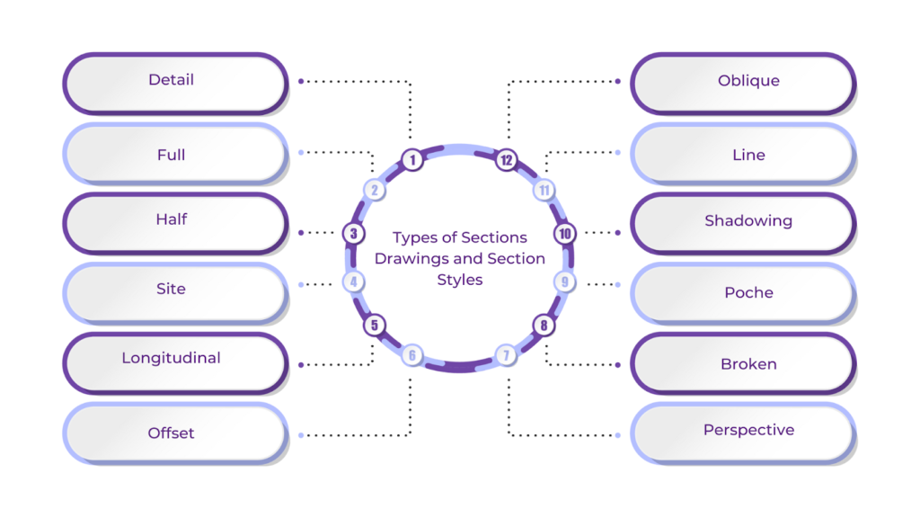
Section drawings come in various types and styles, each serving a particular purpose in design and construction. The type of section depends on what part of the building is shown, such as a full cut of the building, a specific wall detail, or a section that includes the surrounding site.
Section styles refer to how these cuts are represented, using line thickness, hatch patterns, and shading. Choosing the right type and style ensures the section drawing is clear and informative and provides essential details about the building’s layout, materials, and structure.
Below are the main types of section drawings and section styles:
1. Detail
An in-detail drawing focuses on a specific part of a building, showing more detailed views and providing more precise descriptions of the components. A detail section shows how small parts are assembled. These drawings usually include many labels, call-outs, and line styles and patterns to show different materials and parts.
2. Full
Full (or typical) sections have a cutting line that goes through the building or object. They help get a complete inside view of a structure. These sections show the entire building from top to bottom, giving an overview of the outer walls and inner spaces.
3. Half
A half-section cuts through only half of an object, leaving the other half shown as a regular elevation. Thus, only a quarter of the object is cut while the rest remains intact.
In a floor plan, half sections typically feature a section line that turns at a 90-degree angle from the center. This creates an opening that allows you to view both the interior and exterior from one perspective.
4. Site
Site sections cut through the entire site, including the land and terrain, to show how all the buildings in a development are related to each other. They are especially useful for projects with multiple buildings situated close together.
You’ll often see site sections for projects on steep hillsides or by the beach. These sections help reveal the land’s shape, grading, and important features like excavation and underground spaces.
5. Longitudinal
A longitudinal section is a cut along the long side of a structure, showing the entire building from top to bottom. These sections are often used in architectural plans and are usually required for permits and construction.
6. Offset
An offset section uses a cutting line that doesn’t go straight. Instead, the line bends and changes direction to include different parts of the structure in the same view. The changes in direction are usually at right angles to show different depths in the section while keeping the view consistent.
7. Perspective
Perspective sections are mainly used to present ideas and communicate the design to clients. These views show three-dimensional depth beyond the cut, highlighting space, finishes, furniture, people, and light.
8. Broken
A broken section is a view in which some parts are omitted to focus on essential details. Break lines indicate where parts are missing and where the view continues.
This technique allows important details to be shown on a smaller scale without losing key information. Walls and floors are often divided with break lines because they are long and continuous.
9. Poche
Poche shows cut parts in a section by filling, hatching, or shading them, making them stand out from the rest of the drawing. It’s commonly used for floors, walls, and beams.
Different hatch patterns and shading techniques help clarify materials, structural elements, and finishes, making the details easier to understand.
10. Shadowing
Shadowing is used in section drawings to create soft light and dark areas on the inner walls. This technique helps show how light, both natural and artificial, lights up the inside of a building.
11. Line
A line drawing uses only lines, without colour, shading, or shadows. Line sections provide clarity, making it easier to take measurements on-site since the lines are more distinct than solid colours or shadows. Technical construction drawings are often done in this style to ensure all essential details remain visible.
12. Oblique
Oblique sections are created by cutting the building or object at an angle different from the usual horizontal or vertical planes. The section lines are drawn diagonally, which makes them ideal for showcasing round or curved designs that aren’t easily captured in regular cross or longitudinal sections.
Each type and style of section drawing presents building details in a unique way. To fully benefit from these drawings, it’s important to understand how to read them and extract the valuable information they provide.
How to Read a Section in Architecture?
Reading a section drawing may seem complex at first, but with the right approach, it becomes much easier. A section drawing provides a clear view of a building, offering insights into its interior structure, layout, and how different elements work together.
By focusing on key features like walls, doors, windows, and materials, you can clearly understand how the building functions. Additionally, recognising the symbols, notations, and hatch patterns used in the drawing is crucial for accurately interpreting the design and construction details.
Here’s a simple step-by-step guide to help you read a section drawing:
- Identify the Section Line: Locate the section line on the floor plan. This line shows where the building is “cut” and is often labelled with symbols like “A-A” or “B-B” and arrows indicating the view direction.
- Understand the Scale: Look for the scale, which is usually written in the title block. The scale helps you measure floor heights, wall thicknesses, and distances accurately.
- Recognise the Cut Elements: Elements that the section line cuts through, such as walls, floors, and columns, are represented with bold, solid lines or distinct patterns. Items that aren’t cut, like windows or background objects, are typically shown with lighter or dashed lines to differentiate them.
- Interpret the Vertical Dimensions: Check height measurements that show floor levels, ceiling heights, and roof slopes. These help you see how spaces are arranged vertically.
- Analyse Structural Details: Pay attention to details like wall layers, insulation, and how parts are joined. Labels or notes often explain materials and construction techniques.
- Look for Symbols and Notations: Symbols represent features like stairs, windows, and doors, while hatch patterns show different materials like concrete, brick, or insulation.
- Understand Spatial Relationships: See how rooms connect between floors, and look for features like staircases or open spaces. If the section includes the site, it may also show landscaping or retaining walls.
- Identify Mechanical, Electrical, and Plumbing (MEP) Elements: In detailed section drawings, symbols or lines represent systems such as HVAC ducts, plumbing pipes, and electrical wiring.
By following the above steps, you can easily understand the design, materials, and structure of a building from its section drawings. The next step is knowing how to draw these sections accurately to communicate those details.
How Do You Draw a Section in Architecture?
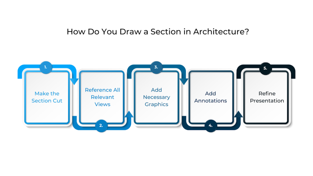
Drawing a section in architecture involves creating a vertical or horizontal cut through a building to reveal its internal structure and spatial relationships. This process needs careful planning to ensure that the section captures the most critical aspects of the design, from floor layouts and wall assemblies to structural components and materials.
To draw a section in architecture, follow these steps:
- Make the Section Cut
The first step is deciding where to make the cut. This means choosing where to place the section line, which way the view will go, and which rooms or important parts you want to show in the drawing. Make sure the section line is placed in the same spot on all floor plans and elevations if needed.
- Reference All Relevant Views
Use the affected views to outline the building and prepare the drawing with the correct measurements and scale. Next, draw the inner components, such as walls, windows, doors, ceilings, hardware, and fixtures. Check the views often to ensure everything is accurate.
- Add Necessary Graphics
After drawing the main components, add hatch patterns to show materials like cut walls, earth, gravel, wood grain, finishes, and insulation.
- Add Annotations
Annotations are an essential part of architectural sections. This is where you add key information like labels, callouts, tags, and measurements.
- Refine Presentation
Whether the section is for construction or presentation, it’s essential to keep it clear and readable. This means cleaning up the lines and choosing easy-to-read fonts for technical drawings. In addition, you can add colour and images to make presentations easier to understand.
Maintaining clarity and readability in section drawings is crucial, whether they’re used for construction or presentations.
How to Improve Your Section Drawings?
Improving your section drawings is essential for making them clearer, more accurate, and more effective in communicating a building’s design and structure. By consistently focusing on the details, these drawings can become a powerful way to showcase both the beauty and functionality of your project.
To help you refine your section drawings and make them even more professional and easy to understand, here are some practical tips:
Choose the Right Section Line Strategically
Place the section line through key building elements, such as staircases, atriums, or connections between different levels. Avoid cutting through empty spaces unless structural details are necessary.
For complex buildings, consider multiple sections to show different views and clearly mark the section line on the floor plan with arrows indicating the view direction.
Include Accurate Dimensions and Annotations
Add clear dimensions for floor-to-ceiling heights, thickness of slabs, wall layers, and stair details. Use standard terms like FFL (Finished Floor Level), SSL (Structural Slab Level), and TOS (Top of Slab). Label important parts, such as walls, materials, and rooms, clearly.
In addition, keep the annotations short but informative to help builders and contractors understand the details easily.
Show Context and Surroundings
In site sections, include details like ground levels, nearby buildings, trees, and slopes. Use lighter lines for these elements so that the building section stands out. In urban contexts, show nearby street levels and the height of surrounding buildings for added context.
Add Textures
Textures can make section drawings look more realistic. You can use them for finishes, skies, roads, grass, and materials to make the drawing more life-like and visually appealing. Textured sections are also easier to understand because they clearly show materials without relying on finish tags or material labels.
Use Cutouts
Cutouts of people, plants, or vehicles can bring sections to life and show how spaces will be used once completed. They can also show how spaces evolve during events or gatherings, adding dynamic elements to the drawing.
Highlight Key Architectural Features
Highlight essential features like staircases, mezzanines, balconies, and double-height spaces. Use callouts or detail sections to emphasise more complex areas, such as window designs or exterior finishes. Indicate how natural light and ventilation move through the building using arrows or shaded areas.
Use Colour and Shading for Clarity
Use light colours or grayscale shading to show different materials and spaces. Apply soft shading to highlight cut areas, leaving the background unshaded. Colour coding is particularly useful for presentations, but avoid using too much colour in technical drawings for construction use.
Add Perspective
Adding perspective to a section view helps show depth and improves the view of interior spaces. A perspective section, whether drawn, modelled, or rendered, creates a sense of depth, pulling lines inward and revealing more interior details. This makes the section feel like a true cut-through of the building.
Maintain Consistency Across Drawings
Ensure consistent use of line weights, symbols, dimensions, and hatching across all section drawings. Match section lines with those in floor plans and elevations, and adhere to standard architectural drawing rules for better clarity. If multiple sections are involved, include a drawing key or legend.
Utilise Modern Software Tools
Use BIM software like Revit or ArchiCAD to create accurate section drawings from 3D models. Tools like AutoCAD, SketchUp, or Rhino help make precise sections and allow you to see them in real time. You can also use plugins like V-Ray for more realistic section views.
Add Human Scale and Furniture
Include scaled human figures to show the size and proportion of spaces. Add furniture and fixtures with lighter lines to show layout and functionality. Using standard symbols for these elements ensures clarity and helps clients visualise the space.
Emphasise Vertical Relationships
Show how floors are connected, especially in multi-level buildings. Use appropriate symbols for staircases, elevators, and mezzanines. Include height markers for level changes and vertical circulation to ensure the building’s flow is fully understood.
Illustrate Natural Light and Ventilation
Use arrows to show how sunlight moves, where natural airflow goes, and where shading devices are placed. For projects focused on sustainability, highlight features like insulation, thermal mass, and natural heating or cooling.
Shading techniques can show how light changes over the day, and diagrams can help explain passive design strategies.
Cross-Reference with Other Drawings
Check section drawings against floor plans, elevations, and detailed drawings to ensure consistency. Correctly label section lines across all sheets and use matching symbols and notations. Misaligned references can lead to confusion during construction.
Get Feedback and Refine
Ask relevant stakeholders, including design team members and senior professionals, to review the drawing to ensure it’s clear and complete. Check with construction professionals to ensure the drawing has enough detail for the project. Learn from each project to improve your future section drawings. Remember to always prioritise simplicity and clarity over too much detail.
BIM Supports GREEN EARTH.

Conclusion
Section drawings are essential in architectural design as they provide a clear view of a building’s internal structure and how spaces are connected. They help explain complex design ideas and make it easier for architects, engineers, and builders to work together, keeping the project aligned with the original plan.
Sections are especially useful for showing vertical relationships, material choices, and structural details that floor plans and elevations may not fully show. By offering this clarity, section drawings help avoid issues during construction and improve the accuracy of the final build.
Are you looking for BIM solutions?
BIM ASSOCIATES is your one-stop BIM Solution provider for the Architecture and Structure discipline. Their solutions help clients with better decision-making, cost-saving, efficient construction planning, and green earth initiatives.
You might also like: Importance of Construction Drawings: Types, Details & Regulations.
FAQs (Frequently Asked Questions)
1. What is a section drawing in architecture?
A section drawing represents a vertical cut through a building, typically along its main axis, though it can be made anywhere. This type of drawing provides a detailed view of both the interior and exterior forms, highlighting interior spaces, walls separating the interior from the exterior, and various other structural details.
2. What are the rules for section drawing?
The rules for section drawing are as follows:
- A section-lined area is always surrounded by a clear outline.
- The section lines in each area should run in the same direction.
- If the lines go in opposite directions, it indicates a different part of the building.
- All visible edges behind the cutting plane should be shown.
- Hidden features are not included in the section view, except for threads and broken-out sections.
3. What are sections aa and bb in the drawing?
SECTION A-A shows the front view of the part, while SECTION B-B shows the right-side view in the drawing.