In 2025, the UK stands out as one of the leading users of Autodesk Revit, with 998 users making up 10.07% of the global customer base. As Revit becomes more widely used, it’s important for these users to learn how to use its features, like the View Range, effectively.
The View Range is key to creating accurate floor plans in Revit, as it determines which elements are visible in your view based on horizontal planes. If the View Range is not set correctly, some elements may be missing, or the view might not appear as intended, impacting the quality of your design.
In this article, you’ll learn what View Range is, how to adjust it for better floor plan clarity, and essential tips to improve visibility. In addition, you’ll also learn how to use Plan Regions for multiple view ranges in a single plan and how to modify the Cut Plane for precise control over displayed elements.
What are the View Range in Floor Plan Views?

In Revit, View Range controls which parts of a floor plan are visible based on their height. It determines how elements appear by setting cut levels and display limits. This is especially useful for multi-storey buildings or areas with different floor heights.
Adjusting the View Range lets you customise visibility and representation in the floor plan, making it easier to document different building levels and elements. It helps control the level of detail and ensures that specific architectural features are displayed correctly based on their height in the model.
Setting up the View Range correctly helps create clear and accurate floor plans, ensuring all important details are displayed properly. To achieve the best results, you need to know how to adjust the View Range settings to meet the needs of your project.
Adjusting View Range in Floor Plan Views
Adjusting the View Range in Revit allows you to control which elements appear in a floor plan based on their height. Adjusting these settings allows you to control how walls, windows, doors, and other components are displayed. This is especially helpful in multi-storey buildings or when showing specific areas.
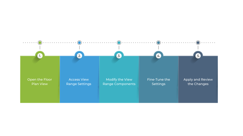
To adjust the View Range in Floor Plan Views in Revit, follow these steps:
- Open the Floor Plan View
Start by selecting the floor plan you want to adjust. This could be a standard floor plan, ceiling plan, or another 2D view.
- Access View Range Settings
Go to the Properties palette and find the View Range under the Extents section. Click Edit to open the View Range dialog box.
- Modify the View Range Components
The View Range settings include four key parts:
- Top: Defines the highest visible point in the view. For example, if you want to see the ceiling, set this to the ceiling height. Anything above this will not be visible unless adjusted.
- Cut Plane: The most important setting, determining where the model is “cut” to show details. Typically set at 4 feet (1.2 metres) above the floor, it ensures walls, doors, and windows are displayed correctly.
- Bottom: Controls the lowest visible point. Adjusting this helps display elements below the cut plane, such as basement walls or foundations.
- View Depth: Extends visibility below the bottom level. This is useful for showing underground elements like footings and plumbing.
- Fine-Tune the Settings
After entering your desired values for Top, Cut Plane, Bottom, and View Depth, you can fine-tune the settings for the view to ensure the appropriate elements are visible. Adjusting the cut plane and view depth ensures you’re showing the right model sections in the floor plan.
- Apply and Review the Changes
Once you’ve made your adjustments, click OK to apply the settings. The floor plan will be updated to reflect the new View Range. Check the floor plan to ensure that the desired elements are displayed correctly and that unwanted elements are hidden.
Fine-tuning the View Range settings helps control visibility in your floor plans, but there are additional strategies that make the process more efficient.
Also read: How to Download and Install Revit on macOS: Solutions & M2 Performance.
9 Tips to Master View Range in Revit
Mastering the View Range in Revit is key to creating clear and accurate drawings. It controls what elements appear in plan views, affecting how your design is displayed. However, many users find it tricky to set up, often leading to missing objects or unexpected visibility issues.
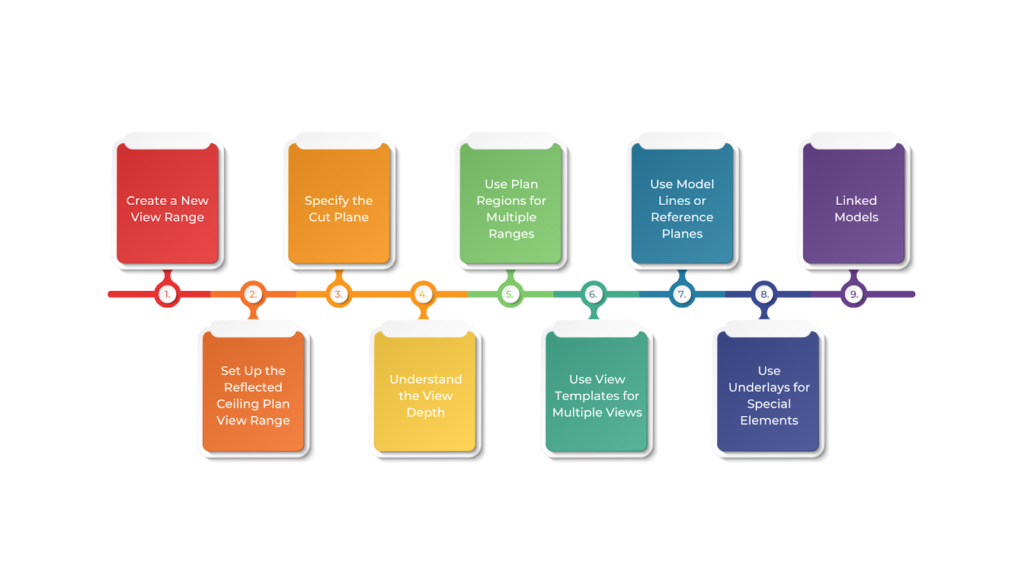
Below are the nine tips to master the view range in Revit:
1. Create a New View Range
You can set a view range for any plan view, including floor plans, ceiling plans, area plans, and structural plans. To set up the view range in your plan view, follow these steps:
- Open a plan view: In the Project Browser, double-click the plan view you want to open.
- Open the View Range settings: In the Properties palette, under Extents, click the View Range edit box (Shortcut: VR).
- Adjust the settings: For floor plans, focus on adjusting the Bottom and Cut planes to control visibility.
- Click OK: The view range controls how elements appear in a plan view using four horizontal planes. Click the “<< Show” button in the dialog box to see a visual preview of these planes.
2. Set Up the Reflected Ceiling Plan View Range
In view of the ceiling plan, the Cut Plane acts as the Bottom Plane and the Bottom Plane is disabled. This means you only need to adjust the Top and Cut planes to control which elements appear as cut or projected.
To set the View Range for Reflected Ceiling Plan (RCP), follow these steps:
- Open the Reflected Ceiling Plan in the Project Browser.
- Press VR on your keyboard to open the View Range settings.
- Set the Top to Level 2 and the Offset to 3.30m.
- Set the Cut Plane to Level 1 and the Offset to 1.40m.
- Click OK to apply the changes.
3. Specify the Cut Plane
The Cut Plane controls which elements are shown as cut in your plan view. However, not all elements can be cut.
Cuttable Categories
Most MEP-F families cannot be cut. Open the Visibility/Graphics dialog (Shortcut: VG) to check which categories can be cut. The Cut column will be grayed out for categories that cannot be cut.
Walls, Columns, Floors, and Stairs
If a wall or column has its Top Constraint set to Unconnected, it might not appear as cut for reasons unknown. To fix this, set the Top Constraint to a level and use a negative offset value if needed.
Each View Range setting affects how different elements appear in plan views. The table below summarises how basic families behave with different view range options.
| Type | Above Cut Plane | At Cut Plane | Below Cut Plane | Crosses Cut Plane |
| Floor/Wall | Shown as Projected | Cut | Shown as Projected | Partially Cut |
| Stair Run | Shown as Projected | Cut | Invisible | Partially Cut |
| Stair Landing | Invisible | Cut | Invisible | Visible |
| Direction Indicator | Invisible | Visible | Invisible | Visible |
4. Understand the View Depth
The View Depth is an extra plane that extends visibility beyond the Bottom Plane in floor plans or above the Top Plane in reflected ceiling plans (RCPs). It controls how far below or above the Cut Plane elements are displayed.
Elements between the Bottom/Top Plane and View Depth appear in the plan view using the “Beyond” line style (which is solid by default).
To set the View Depth, you need to define its height relative to a level or as an offset from a level. If you don’t want to limit it, you can set it to “Unlimited.”
5. Use Plan Regions for Multiple Ranges
Plan Regions let you adjust the View Range in specific parts of a view. This is helpful when you need to show elements that are above or below the main View Range without changing the entire plan.
6. Use View Templates for Multiple Views
Once you’ve adjusted your View Range, you can save it as a View Template to use in other views. View Templates store and reuse view settings, making it easy to apply the same properties to different views.
To create a View Template, follow these steps:
- Head to the View tab > Graphics panel > View Templates drop-down menu.
- Click Create Template from Current View.
- Enter a name for your template.
- Under View Properties, click the View Range edit box.
- Adjust the View Range settings and click OK.
- In another view, open the View Templates menu.
- Click Apply Template Properties to Current View.
You can create templates for common view types, like floor plans, ceiling plans, and site plans, and quickly apply them to new or existing views.
7. Use Model Lines or Reference Planes
To visually check and adjust the View Range, draw three markers (model lines or reference planes) in a section view to represent the Top, Cut, and Bottom planes. These markers act as guides in 3D views.
To see a Reference Plane in 3D, follow these steps:
- Go to the Architecture tab > Work Plane panel > click Show.
- Open the Set menu and click Set Work Plane.
- Select the new reference plane and click OK.
8. Use Underlays for Special Elements
An underlay lets you display elements that are outside your View Range but still important for your plan view. For example, you can use an underlay to show a ceiling grid or roof structure in a floor plan. This lets you see elements from other levels without changing your View Range settings.
9. Linked Models
Check the View Range settings of linked models regularly to ensure they match your host model. A mismatch can cause elements to display incorrectly.
To transfer all view templates to another project:
- Open both project files.
- Go to the Manage tab > Settings panel > select Transfer Project Standards.
- In the Copy from drop-down menu, select the project file.
- Check View Templates and click OK.
To transfer only one view template, first Save As the main project, delete all other templates, and then use the Transfer Project Standards method.
If you’re linking to a project where views have been modified:
- Head over to the View tab > Graphics panel > click Visibility/Graphics (Shortcut: VG).
- In the Revit Links tab, click the file’s Display Settings box.
- Select By Linked View to match the host model.
For more control, choose Custom to display only the View Range from the linked project. This ensures consistency and accuracy across models. In some cases, a single View Range may not be enough to display all the necessary details in a floor plan. Certain areas may require different visibility settings to show specific elements accurately.
Ready to simplify your projects and achieve the benefits?
BIM ASSOCIATES is your one-stop BIM Solution provider for Revit Architectural and Structural Solutions. They coordinate with your team to develop, record, and streamline the BIM Revit Model, along with the sheets, Bill of Quantities, Bill of Materials, and clash coordination.
Create Plan Regions in Revit (Multiple View Ranges)
Plan Regions in Revit helps you show different view heights within the same floor plan. This is useful when parts of a building have different ceiling heights or when certain elements must be displayed at different cut levels.
Instead of changing the view range for the whole plan, you can create a Plan Region to adjust the view for a specific area. This makes it easier to display all necessary details without affecting the rest of the floor plan.
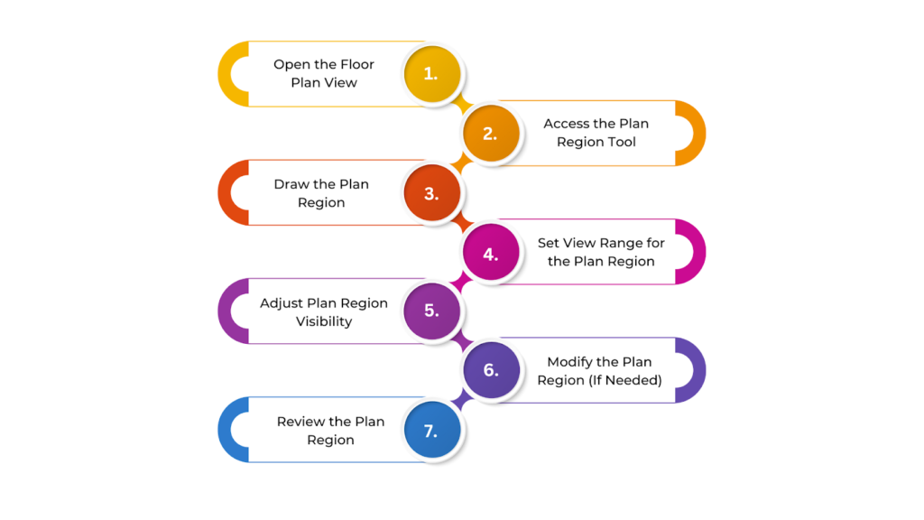
To create Plan Regions in Revit, follow these steps:
- Open the Floor Plan View
Start by opening the floor plan where you want to create the Plan Region. This could be any level or reflected ceiling plan.
- Access the Plan Region Tool
Go to the View tab on the ribbon. In the Create panel, click Plan Region. You can also right-click within the drawing area or use the Project Browser to select Plan Region.
- Draw the Plan Region
After selecting Plan Region, your cursor will change, allowing you to start drawing. Click to define the boundaries—you can draw a rectangle, polygon, or irregular shape. The Plan Region should cover the area where you need a different View Range.
- Set View Range for the Plan Region
Once the Plan Region is drawn, a dialog box will appear. Adjust the Top, Cut Plane, Bottom, and View Depth settings for that specific area. For example, lower the Cut Plane to show the foundations or raise it for areas with high ceilings.
- Adjust Plan Region Visibility
Modify its visibility and graphic settings to prevent conflicts with the rest of the view. You can hide the Plan Region boundaries in the final sheet view using Visibility/Graphics settings (Shortcut: VG).
- Modify the Plan Region (If Needed)
Select the Plan Region to resize or reshape it. To update its View Range, select it and click Edit in the Properties palette.
- Review the Plan Region
Check the plan to ensure elements inside the Plan Region appear correctly. Make sure the transition between different View Ranges is smooth. This method ensures that specific areas are displayed correctly without affecting the entire floor plan.
Fine-tuning the View Range with Plan Regions helps display different areas accurately, but sometimes adjusting the Cut Plane itself is necessary.
How to Change the Cut Plane in Revit?
Changing the Cut Plane in Revit helps control how elements appear in floor plans, sections, and other views. It sets the height where the model is “cut” to show internal elements like walls, doors, and windows.
By adjusting the Cut Plane, you can fine-tune what is visible in your view, ensuring the right details are displayed.
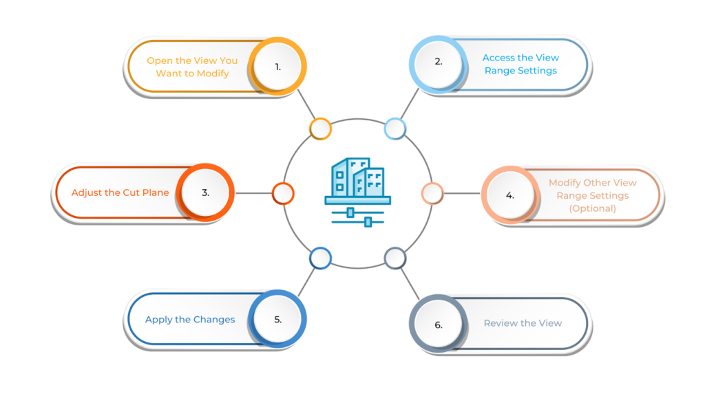
To change the Cut Plane in Revit, follow these steps:
- Open the View You Want to Modify
Open the floor plan or section view where you want to change the Cut Plane.
- Access the View Range Settings
In the Properties palette, scroll to View Range under the Extents section. Click Edit to open the View Range settings.
- Adjust the Cut Plane
In the View Range dialog box, find the Cut Plane setting. Change its height to adjust where the model is “cut” in the view. The default Cut Plane height is usually 4 feet (1.2 metres) for floor plans, but in commercial buildings, you may need to raise it to 5 feet (1.5 metres) or more to capture taller elements. Set it at a height where it clearly displays doors, windows, and internal walls.
- Modify Other View Range Settings (Optional)
You can also adjust the Top, Bottom, and View Depth settings to refine visibility. The Top defines the highest visible point (such as a ceiling or roof), the Bottom sets the lowest visible point (like the floor or foundation), and the View Depth controls how far below the Bottom Plane elements remain visible.
- Apply the Changes
Click OK, and the view will update based on the new Cut Plane settings.
- Review the View
Check if the correct elements appear. If needed, adjust the Cut Plane again until you get the desired result.
If needed, adjust the Cut Plane, Top, Bottom, or View Depth settings to improve the view. This process helps ensure your floor plans and sections are displayed clearly and accurately, meeting the specific needs of your design.
BIM Supports GREEN EARTH.
Conclusion
Understanding and adjusting View Range in Revit is key to creating clear and precise drawings. By setting the Cut Plane, View Depth, Top, and Bottom correctly, you can control which elements appear in your floor plans and sections. This helps communicate your design clearly, reducing errors and improving documentation.
Practicing with View Range settings will help you avoid visibility issues and keep your plans well-organised. Try different configurations for various views and floor plans. With experience, you’ll be able to fine-tune each view to show exactly what’s needed, improving the quality of your work.
Are you looking for BIM solutions?
BIM ASSOCIATES is your one-stop BIM Solution provider for the Architecture and Structure discipline. Their solutions help clients with better decision-making, cost-saving, efficient construction planning, and green earth initiatives.
You might also like: Revit Tutorial: Elevation Views, Levels, and Spot Elevations Guide.
FAQs (Frequently Asked Questions)
1. What is the view range in the floor plan?
The view range consists of horizontal planes that control what you can see in a plane view. It defines which elements are visible and how they appear based on their height relative to these planes. The main planes are the Top, Cut Plane, and Bottom.
2. What is the shortcut for view range in Revit?
To quickly access the View Range settings, go to the Properties palette under Extents and click the View Range edit box (Shortcut: VR).
3. What is the view of a floor plan?
A floor plan is a 2D representation of a building’s interior, viewed from above, showing walls, doors, windows, and other features. It’s created by projecting the building’s features onto a horizontal plane at a specific height.

