
In 2025, the UK stands out as one of the leading adopters of Autodesk Revit, with 1,196 users accounting for 10.46% of the global customer base. This prominence underscores the growing reliance on Revit’s powerful tools to simplify architectural design processes. Among these tools, creating elevation views and adding levels are foundational features that enhance the organization and visualization of designs.
Elevation views provide a clear perspective of a building’s vertical dimensions, helping architects and designers communicate critical aspects of the structure. Levels, however, serve as indispensable reference points for placing and aligning elements like walls, floors, ceilings, and structural components, ensuring consistency and accuracy throughout the project.
Whether you are a beginner or an experienced Revit user, this guide will help you enhance project accuracy and streamline your workflow. This article covers everything you need to know, from crafting elevation views to placing and modifying levels, setting customisation options, and using spot elevations for precise height annotations.
Creating Elevation Views in Revit
Creating elevation views in Revit helps visualise a building’s vertical structure and coordinate designs across multiple disciplines, such as architecture, structural engineering, and MEPF.
These views enable designers to highlight materials, textures, and intricate details, clearly representing the project’s aesthetics and functionality. With Revit’s intuitive tools, you can efficiently generate, customise, and manage elevation views, ensuring seamless integration into the project workflow.
The key steps to create and manage elevation views in Revit are as follows:
- Open Elevation Views in the Project Browser
The Project Browser in Revit serves as a central hub, organising all views, sheets, and families within your project. To locate and access elevation views:
- Navigate to the Project Browser: Locate the Project Browser on the left side of your screen.
- Find the Views Section: Scroll through the Project Browser to locate the Views section.
- Locate the Elevations Category: Under the Views section, find the Elevations category.
- Expand the Elevations Category: Click the arrow or plus sign next to the Elevations category to view predefined elevation views (e.g., North, South, East, West).
- Open the Desired Elevation View: Double-click the elevation view you want to open. It will appear in the main workspace.
If you can’t see the elevation views in the Project Browser, ensure they are enabled in the view settings. Also, check that the elevation markers are correctly placed in the plan view.
- Create & Customise Elevation Views in Revit
The Elevations tool in the Architecture tab allows you to create new elevation views. Place elevation markers in your floor plan to define your desired views, such as interior or exterior perspectives. These markers include directional arrows that you can activate or deactivate based on your requirements.
To create and customise elevation views, follow these steps:
- Locate the Elevations Tool: Open the Architecture tab on the ribbon. In the View panel, select Elevation.
- Place an Elevation Marker: Click on the floor plan to position an elevation marker. Enable or disable the directional arrows as needed.
- Adjust the View Range: Use the Properties palette to modify the view range and crop region, ensuring relevant project elements are included.
- Customise the Elevation View: Double-click the elevation arrow in the plan view to open the elevation. Refine the view using Line Weights, View Templates, and Visibility Graphics.
Following these steps allows you to effectively create & manage elevation views in Revit, ensuring a clear and accurate representation of your design.
Establishing detailed elevation views sets the foundation for a well-organised project, while creating and managing levels is equally important, as they define floors, ceilings, and other key structural elements.
Creating Levels in Revit
Levels are a key element in Revit, providing reference points for floor plans, elevations, and sections. They define building heights, ensuring consistency and accuracy across your design. Levels establish a structured framework that organises and manages your project, enabling you to precisely place architectural and structural elements like walls, floors, and ceilings.
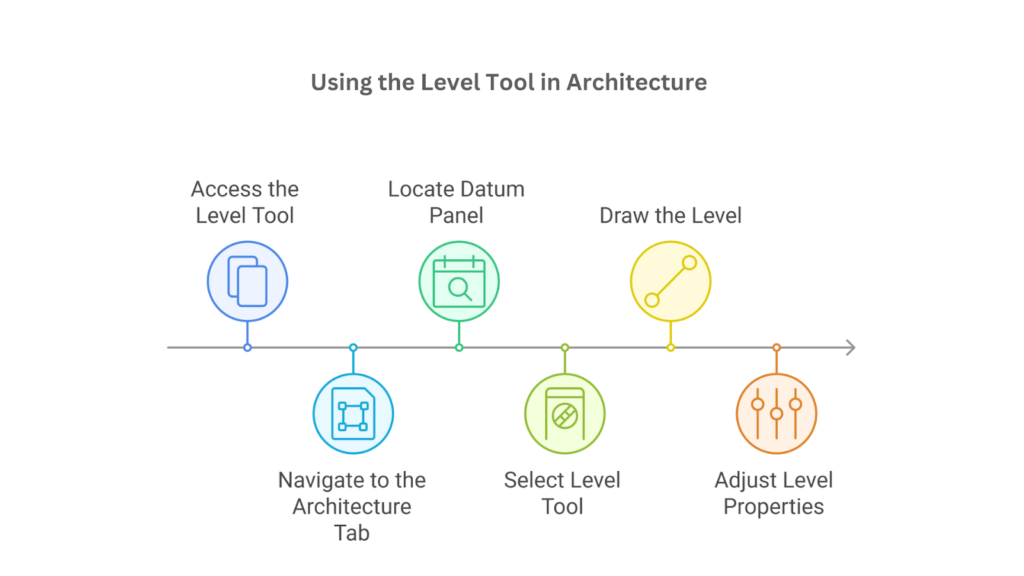
The steps to create levels in Revit are as follows:
- Access the Level Tool
Open an Elevation View or Section View to define vertical dimensions and prepare the workspace.
- Navigate to the Architecture Tab
Go to the top ribbon menu and click on the Architecture tab.
- Locate Datum Panel
Within the Architecture tab, find the Datum panel containing tools like grids and levels.
- Select Level Tool
Click on the Level tool to activate it, changing the cursor to Level creation mode.
- Draw the Level
In the Elevation or Section View, click to define the start point, drag horizontally, and set length.
- Adjust Level Properties
Use the Properties palette to modify level attributes such as name and elevation.
After following these steps, you can effectively create levels in Revit, providing accurate reference points for your project’s vertical structure and layout. Once you’ve established the basics of creating levels, you can further enhance your project by adding multiple levels efficiently.
Adding Multiple Levels in Revit
Adding multiple levels simultaneously streamlines the setup of complex vertical designs, such as multi-story buildings or tiered structures. Revit offers tools like the Copy and Array commands to duplicate levels with consistent spacing and alignment.
Efficiently managing multiple levels provides a solid framework for placing architectural and structural elements, improving project organisation and workflow.
The steps to add multiple levels in Revit are as follows:
- Open an Elevation/Section View: Open an Elevation or Section View to manage and view the vertical dimension of your project where levels are adjusted.
- Access the Level Tool: Navigate to the Architecture tab on the ribbon and select the Level tool from the Datum panel.
- Create the First Level: Click in the view to set the level’s starting point, drag horizontally to set the desired length, and click to finalise placement.
- Use Copy or Array Tool: Select the level, use the Copy tool (or shortcut CO), specify vertical spacing, and click to duplicate levels. Or, Use the Array tool to create multiple evenly spaced levels by specifying the number and spacing.
- Adjust Level Properties: Click on level names in the Elevation View or Project Browser and assign meaningful names. Adjust heights directly using the Properties palette or level tags.
- Create Associated Plan Views: When creating levels, ensure the Make Plan View checkbox is selected. If omitted, manually add plan views via View > Plan Views > Floor Plan.
Tools like Copy and Array quickly create and arrange multiple levels in Revit. This ensures precise alignment and accurate documentation throughout your project. While adding multiple levels establishes the foundation for your project, customising their settings allows you to tailor each level to meet specific design needs.
Also read: Autodesk Revit 2025 Features & Benefits: A Detailed Guide
Setting Options for Levels in Revit
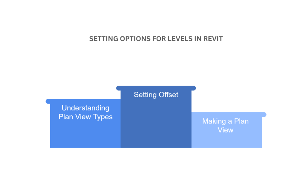
When working with levels in Revit, you can customise various options to suit your project requirements. These include creating associated plan views, selecting plan view types, and adjusting offsets. Customising these options improves the organisation of your project and the efficiency of the design process.
To set these options for levels, follow these steps:
- Making a Plan View
When creating a new level, you can automatically generate a corresponding plan view. This feature ensures every level has an associated plan for detailed design and documentation. Automatically generating a plan view lets you start working on layouts, placing elements such as walls, doors, and furniture without manually creating a view later.
To enhance organisation and clarity, Revit provides options to enable plan view creation and customise level tags for better visualisation:
- Enable Plan View Creation: After drawing a level, Revit prompts you to create a new Floor Plan or Ceiling Plan. Ensure “Make Plan View” is checked to create an associated plan.
- Customise Level Tag Colour: Differentiate levels visually by setting a specific Level Tag Colour. Select the level tag, navigate to Properties, and adjust under Visibility/Graphics Overrides.
- Understanding Plan View Types
Revit offers various options for creating different types of plan views associated with a level. Depending on your project’s requirements, you can create either or both types for a comprehensive view of each level. These plan view types include:
- Floor Plan: A horizontal slice through the building, showing elements like walls, doors, furniture, and other architectural components.
- Ceiling Plan: Displays the ceiling layout, including lighting fixtures, HVAC components, and other elements near or on the ceiling.
- Both Floor and Ceiling Plans: Create both plan types simultaneously to capture all aspects of the level. Use View Templates to customise display settings for each view type.
Revit also allows you to apply View Templates to customise the appearance and settings of these views, ensuring consistency and clarity throughout your documentation.
- Setting Offset
You can adjust a level’s vertical position by modifying its offset relative to its reference point or callout. This adjustment is beneficial when working with designs that include mezzanines, split levels, or varying floor heights. It ensures that the level aligns with the intended design requirements and maintains consistency throughout the project.
To ensure precise alignment and accommodate varying floor heights, Revit provides an offset feature that adjusts the vertical position of levels relative to their reference points:
- Adjusting the Offset: Select the level line in the Elevation View or Section View. In the Properties palette, locate the Offset parameter. Enter a positive value to raise or a negative value to lower the level.
- Practical Use of Offset: Use offsetting for mezzanines, raised platforms, or sublevels that do not align with the standard heights.
Always confirm the alignment of levels after adjusting the offset to ensure they match design requirements. When you’re coordinating offsets across multiple views, utilise view templates and gridlines for additional precision.
The offset feature ensures precise adjustments and accurate level management in Revit projects. However, achieving a well-structured model involves more than fine-tuning offsets. Understanding how to place efficient and complete levels is equally important, as these serve as the backbone of your design framework.
Want to streamline your workflows and unfold the full potential of Revit?
BIM ASSOCIATES is your one-stop BIM Structural Solution provider for Revit Architectural and Structural Solutions. They coordinate with your team to develop, record, and streamline the BIM Architectural and Structural Revit Model, along with the sheets, Bill of Quantities, and Bill of Materials, as well as clash coordination.
Placing and Completing Levels in Revit
Levels in Revit create horizontal reference planes essential for organising and managing building components. Placing levels accurately ensures all building elements are aligned and coordinated across different floors and sections.
These reference planes act as anchors for structural, architectural, and mechanical components, simplifying the modelling process and enhancing project consistency.
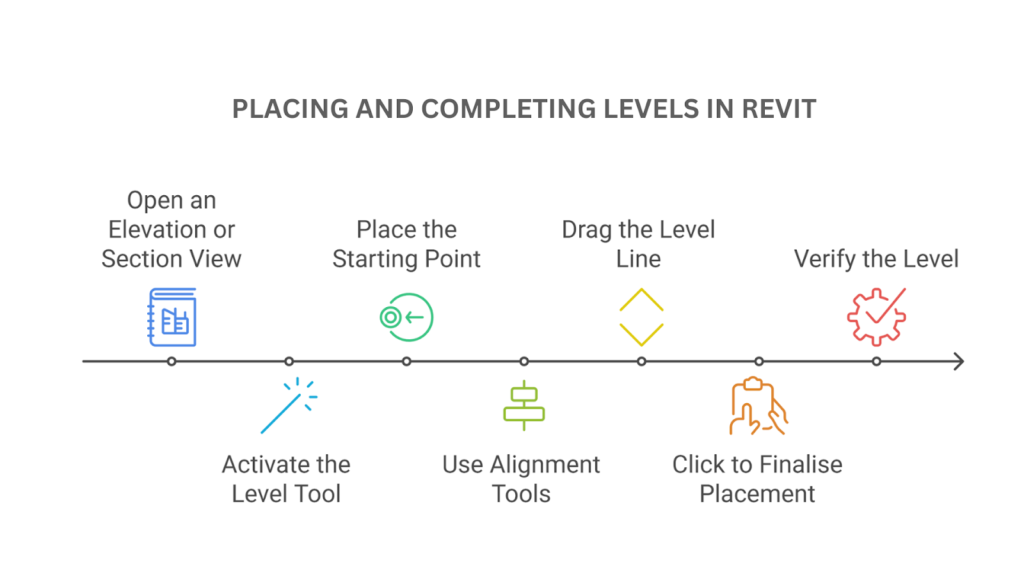
The key steps to place and complete levels in Revit are as follows:
- Open an Elevation or Section View: Navigate to an Elevation or Section View to work within the vertical dimensions of the project.
- Activate the Level Tool: Go to the Architecture tab, locate the Datum panel, and select the Level tool.
- Place the Starting Point: Click anywhere in the view to place the level’s starting point, ensuring alignment with existing levels or grids.
- Use Alignment Tools: Utilise Revit’s snapping and alignment aids to position the level accurately for consistency.
- Drag the Level Line: Drag the cursor horizontally to set the level’s length after placing the starting point.
- Click to Finalise Placement: Click at the endpoint of the callout to complete the level placement; Revit generates the level line and tag.
- Verify the Level: Confirm the level’s placement and alignment, adjusting its position or length using grip handles if needed.
Following these steps will help you effectively place and complete levels in Revit, ensuring they are aligned and serve as reliable reference points for your project.
Once your levels are in place and fully established, fine-tuning their parameters becomes essential for adapting them to your project’s unique requirements. Modifying these parameters enhances accuracy and ensures seamless integration with other project elements.
Modifying Level Parameters in Revit
Levels in Revit are dynamic and can be customised to accommodate design changes or project requirements. Adjusting level parameters allows you to refine their properties to align with evolving project needs.
Customising levels ensures flexibility and adaptability, enabling efficient coordination between architectural, structural, and MEP systems throughout the project’s lifecycle.
To efficiently modify level parameters in Revit, follow these steps:
- Access an Elevation View: Open an Elevation or Section View to view and modify levels.
- Select the Level: Click on the level line or tag to activate it. The level will be highlighted, allowing you to edit its associated parameters.
- Adjust Level Line Length: Use the grip handles to extend or shorten the level line, aligning it with grids or other elements for consistency.
- Edit in the Properties Palette: Open the Properties palette with the level selected to modify parameters such as elevation height, view range, and associated view types.
- Modify Through the Level Tag: Edit the elevation value displayed on the level tag directly by clicking the text field and inputting a new value. The level updates automatically.
- Rename Levels: Click on the level name in the elevation view or Project Browser to rename it. Use descriptive names for clarity (e.g., “First Floor” or “Roof Level”).
- Adjust Using Temporary Dimensions: Edit temporary dimensions displayed when the level is selected to adjust its height relative to other reference points; the level updates instantly.
By applying these methods, you can efficiently modify level parameters in Revit, ensuring they align with your project’s requirements and are easy to manage.
After customising level parameters to suit your project, you must delve into elevation settings. These settings are key in defining vertical relationships and ensuring that all levels are accurately positioned within the design framework.
Adjusting Elevation Level Settings in Revit
Elevation levels in Revit are crucial in accurately defining a building’s vertical position relative to reference points, such as the project base point or survey point. Properly adjusting elevation level settings ensures all building components are aligned correctly within the model and in real-world coordinates.
This precision is vital for seamless integration across structural engineering and site planning disciplines. To manage and adjust the elevation level settings in Revit, follow these steps:
- Access the Elevation View
Open an Elevation or Section View to view the levels and their elevation values relative to the project datum. And, click on the level line to activate it.
- Adjust Elevation in Properties
Use the Properties palette to modify the Elevation field. Enter a new value to set the level’s vertical position, and it will adjust accordingly.
- Align with Design Requirements
Ensure levels correspond to the desired design elevations or construction requirements.
- Understand Reference Points
The Project Base Point is the internal starting point for building measurements, typically 0’0”. Survey Point is also a real-world reference for geolocation.
- Choose Elevation Base
Select the level line, go to Properties, and locate the Elevation Base parameter.
- Set Elevation Base
Choose Project Base Point to measure elevations relative to the internal reference. Select Survey Point to align with site measurements.
- Verify Consistency
Ensure all levels use the correct base point to maintain alignment and accuracy in project and site coordinates.
Managing building elevations using the Properties Palette and carefully setting the elevation base ensures accuracy and alignment in your Revit project.
After ensuring precise elevation settings, it’s essential to consider how levels are visually and informationally represented. Editing level tags allow you to convey critical details effectively, making the model easier to interpret and work with across various teams.
Editing Level Tags in Revit
Level tags in Revit offer essential information and can be customised to enhance clarity and functionality in project documentation. These tags are crucial in improving communication among team members and across disciplines, simplifying the coordination of design elements, and ensuring consistency in project deliverables.
To edit and adjust the level tags effectively, follow these steps:
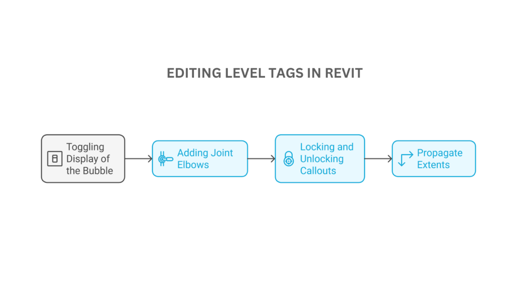
- Toggling Display of the Bubble on Level Callouts
Revit provides flexibility in controlling the display of bubbles on level callouts, allowing you to manage the visual presentation of levels in different views. Depending on the clarity and detail required for the specific view, you can toggle the bubble display on one or both ends of a level line.
Revit offers simple tools that allow you to customise their visibility and content to suit your documentation needs. To adjust the bubble display:
- Access the Level Callout: Select the level line in an Elevation or Section View.
- Toggle Bubble Display: Click the small checkbox at either end of the level line to show or hide the bubble. You can display the bubble at one or both ends of the level for better clarity.
- Adjust Bubble Content: When the bubble is visible, the level name and elevation value will be shown. You can modify these details directly on the tag or through the Properties palette.
These adjustments ensure that your level callouts remain clear and provide only the necessary information, improving the overall readability of your project documentation.
- Adding Joint Elbows in Level Lines
Joint elbows in level lines provide flexibility in managing overlapping or crowded annotations, especially in complex projects with multiple closely spaced levels. Properly using joint elbows helps maintain a clean and organised presentation, ensuring all level information remains accessible and visually distinct.
Revit allows you to add joint elbows to enhance the clarity and organisation of level lines in your views, making it easier to manage overlapping annotations. To add and adjust joint elbows effectively:
- Enable Elbow Option: Select the level line in the view and click on the Add Elbow grip point near the line’s middle.
- Drag to Create Joint: Move the elbow to the desired location to create an angled joint in the level line.
- Use for Complex Layouts: Elbows are helpful when multiple levels overlap or to minimise visual clutter in your documentation.
Incorporating joint elbows ensures your level annotations remain clear and legible, even in highly detailed or crowded views.
- Locking and Unlocking Callouts for Independent Movement
In Revit, locking and unlocking callouts control their movement and alignment within a view. When a callout is locked, its position remains fixed relative to the associated level line, ensuring consistency and preventing accidental adjustments.
Unlocking a callout, on the other hand, allows for independent movement. This enables you to reposition it as needed to improve clarity or fit the layout of your documentation better.
To lock or unlock callouts in Revit for independent adjustment:
- Select the Level Tag: Click on the level callout or bubble to select the Level tag.
- Lock or Unlock Callout: Use the lock icon or the tool in the Modify panel. Locking the callout keeps it in place, while unlocking it allows for movement or repositioning.
- Reposition Independently: Once unlocked, you can move the bubble or tag independently from the level line. This makes it easier to align the tags neatly for better readability.
After using this feature, you can maintain a clean and organised view appearance, ensuring clear and professional documentation.
- Propagate Extents
The Propagate Extents feature in Revit allows you to apply the view-specific adjustments of level lines across multiple views. It saves time and ensures uniformity in your project documentation, reducing the need for repetitive manual adjustments across different views. To use this feature effectively:
- Select Levels: Select one or more levels (hold CTRL and left-click to select multiple).
- Navigate to Propagate Extents: Go to the Modify | Levels tab > Datum panel > click Propagate Extents.
- Select Views: Select the views to match the appearance of their elements.
- Confirm Changes: Click OK to apply the changes.
The appearance of datum elements in different views is not linked. After each edit or move, you must use the Propagate Extents tool again. If the Propagate Datum feature doesn’t work for some views, disable view crops and scopes, then try again.
While managing datum elements ensures consistency across views, there are instances where precise vertical measurements are required within a specific view. This is where spot elevations become invaluable, providing accurate annotations for key points in your model.
How To Use Spot Elevations in Revit?
Spot elevations in Revit are used to annotate and display the vertical height of specific points in a model, such as floors, slabs, or other critical elements. They provide precise information about elevation values, which is essential for detailed documentation and effective communication across disciplines.
To leverage spot elevations in your Revit project, follow these steps:
- Accessing the Spot Elevation Tool: Navigate to the Annotate tab on the ribbon. In the Dimension panel, select Spot Elevation to activate the tool.
- Placing a Spot Elevation: Choose a view such as a Floor Plan, Elevation, Section, or 3D View. Hover over a surface and click to place the annotation.
- Adjust Placement Options: Use the Options Bar to toggle edge, face, or point-based placement methods.
- Modifying Spot Elevation Properties: Select the spot elevation to activate it. Use the Properties palette to adjust the Leader Line, Text Size, or Units Format.
- Editing Elevation Value Display: Use the Properties palette to customise whether the elevation displays absolute, relative, or project base point values.
- Managing Visibility and Graphics: Adjust visibility through Visibility/Graphics Overrides (VG) to ensure visible spot elevations. Apply View Templates for consistency.
Following these steps allows you to efficiently place and manage spot elevations, ensuring accurate and precise documentation of critical height information throughout your project. BIM Supports GREEN EARTH.

Conclusion
Creating and modifying levels accurately in Revit ensures precision and seamless coordination across all project views. Leveraging tools like the Level tool, customising level parameters, managing elevation settings, and using Propagate Extents and spot elevations allow you to streamline workflows and improve project clarity.
Well-structured levels and elevation settings form the backbone of a strong design framework. They promote smooth collaboration among team members and ensure clear, professional documentation. Refining these foundational elements lays the groundwork for a successful and well-coordinated project.
Are you looking for BIM solutions?
BIM ASSOCIATES is your one-stop BIM Solution provider for the Architecture and Structure discipline. Their solutions help clients with better decision-making, cost-saving, efficient construction planning, and green earth initiatives.
You might also like: Bill of Quantities (BOQ): Purpose, Types, & Creation Process Explained.
FAQs (Frequently Asked Questions)
1. How to add spot elevation in Revit?
If you want to add a spot elevation in Revit, follow these steps:
- Open the desired view (e.g., floor plan or section).
- Go to the Annotate tab and click on Spot Elevation.
- Click on the point where you want to place the elevation.
- Adjust the placement as needed by dragging the elevation symbol to the desired location.
- If required, customise the elevation settings through the properties panel for font, size, or other adjustments.
2. How to elevate a building in Revit?
If you want to elevate a building in Revit, follow these steps:
- In the floor plan or 3D view, select the building or elements you want to elevate.
- Go to the Modify tab and click Move.
- Click a point to define the base for the move (e.g., the bottom of the building).
- Drag the building vertically to the desired elevation or type in the exact value in the properties or options bar.
3. What is a spot elevation?
A spot elevation shows the exact elevation of a chosen point. It helps measure elevation points on ramps, roads, toposolids, and stair landings. Spot elevations can be placed on non-horizontal surfaces and non-planar edges.