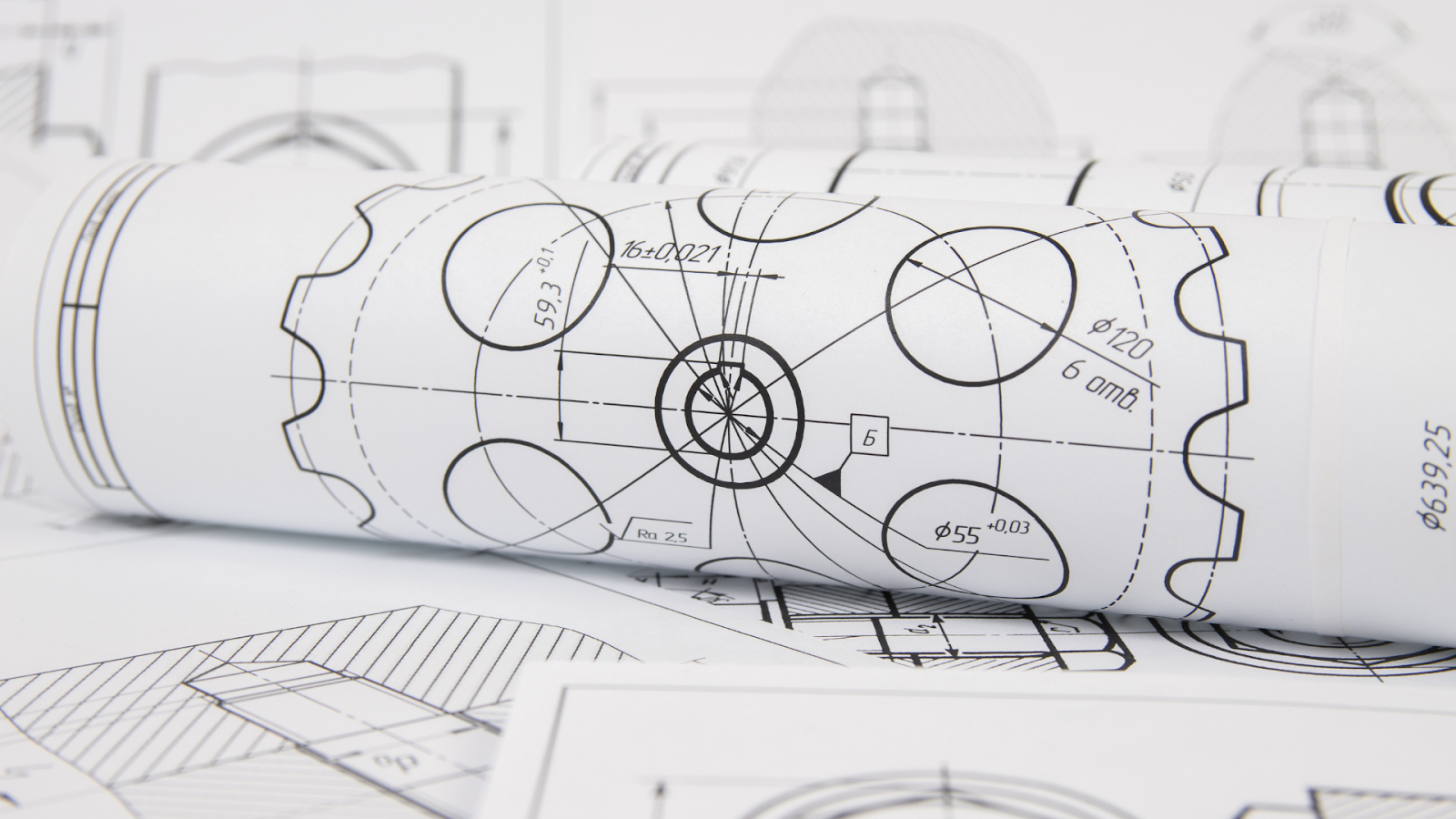
In modern construction, precision is crucial, as even a small miscalculation can cause costly delays and errors. That’s where shop drawings come in. These detailed technical drawings connect design and construction, giving contractors, fabricators, and installers the exact specifications needed to complete a project accurately.
Unlike general construction drawings, shop drawings focus on the finer details, connections, showing materials, dimensions, fabrication methods, and installation instructions.
In this article, you will learn about shop drawings, their role in improving construction projects, their key components, different types, and the creation process. In addition, you’ll explore some expert tips to improve the quality and accuracy of shop drawings which make them more effective for any construction project.
What are Shop Drawings?

Shop drawings are detailed plans and elevations, sections created by BIM contractors, subcontractors, or suppliers to show how specific parts of a construction project will be built, assembled, and installed. They provide more precise details than general design plans, focusing on materials, dimensions, installation methods, and connections.
Before construction starts, architects or engineers review and approve shop drawings to ensure they are accurate and match the project’s design. This helps prevent errors and keeps the work running smoothly.
Various types of drawings are used during a construction project, each serving a specific purpose.
Comparison of Design Drawings, BIM Drawings, and Shop Drawings
In construction and engineering, different types of drawings are used at various stages of a project. Design drawings, BIM drawings, and shop drawings each serve a specific purpose in turning ideas into reality. BIM drawing can also be called detail design drawings or DD Stage set.
Design drawings focus on the overall look and concept, BIM drawings improve teamwork and coordination using digital models, and shop drawings provide exact details for making and installing components. Knowing these differences helps architects, engineers, and contractors work efficiently and ensure accurate project execution.
Below are the differences between design drawings, BIM drawings, and shop drawings:
| Criteria | Design Drawings | BIM Drawings | Shop Drawings |
| Purpose | To outline the general design intent and concepts for a project. | To provide a 3D, detailed, and accurate digital representation of the project, allowing for collaboration and visualisation. | To provide precise, construction-level details for fabrication, installation, and construction purposes. |
| Content | Basic layout, dimensions, materials, and design features. | Detailed 3D models with real-time data for every component, including systems and structure. | Specific details on the construction or fabrication of individual components, showing dimensions, materials, and assembly instructions. |
| Scope | High-level overview of the project design. | Detailed and fully integrated project model, covering all aspects (architecture, structural, mechanical, etc.). | Focused only on particular components or elements of the project, often customised for contractors or fabricators. |
| Stage in Project | Initial phase of the project before construction. | During design and pre-construction phases for planning, coordination, and collaboration. | Late stage, typically after design and when construction is about to begin or in progress. |
| Use | Guides the overall design process. | Enables coordination between teams and disciplines and allows for clash detection and simulations. | Used by contractors and manufacturers for constructing, fabricating, and assembling specific project elements. |
| Format | 2D drawings (plan, elevation, sections) with limited detail. | 3D models (can be in multiple software formats, like .RVT for Revit). | 2D drawings or diagrams with detailed fabrication and installation instructions. |
| Details | General and broad, often with minimal detail. | Very detailed, capturing full geometries, materials, and real-world data. | Extremely detailed, focusing on exact measurements, installation guides, and fabrication specs. |
| Collaboration | Limited collaboration, mainly between the design team. | High collaboration, allowing various teams (architects, engineers, contractors) to work together. | Typically developed with input from contractors, fabricators, and suppliers. |
| Accuracy | May lack precise details for construction purposes. | Highly accurate due to the integration of all systems and components. | Extremely accurate, as they provide the exact dimensions and materials required for construction. |
| Examples | Floor plans, elevations, sections, and schematics. | Virtual building models showing walls, MEP-F systems, and structural elements. | Structural steel details, HVAC ducting plans, custom cabinetry, and electrical panel layouts. |
Each type of drawing is essential in the construction process, but shop drawings stand out for their level of detail and precision. They fill the gap between design intent and actual construction, ensuring that every component is fabricated and installed correctly.
How Shop Drawings Improve Construction Projects?
Shop drawings play a crucial role in construction. They give clear instructions on how specific parts, like HVAC systems and steel reinforcements, will be built and installed.
Accurate shop drawings help ensure every detail is well-planned and correctly executed, reducing errors, avoiding costly delays, and improving coordination between architects, engineers, contractors, and suppliers.
Shop drawings enhance construction projects by:
- Improved Communication Among Teams: Provides clear, detailed visuals that align with architectural and engineering plans, reducing misunderstandings and costly mistakes.
- Precision and Accuracy: Offers highly detailed specifications for fabrication and installation, reducing on-site adjustments and delays.
- Early Problem Detection: Identifies design conflicts before construction starts, preventing costly rework.
- Improved Trade Coordination: Helps different teams, such as electrical, plumbing, and HVAC, integrate their work smoothly.
- Efficient Material and Equipment Procurement: Specifies exact quantities and types of materials, preventing shortages and delays.
- Ensuring Compliance with Codes and Standards: Helps confirm that installations meet legal and safety regulations before construction begins.
- Reduced Risk of Rework and Delays: Provides accurate installation details, reducing the chances of errors that could lead to costly rework.
- Valuable Documentation for Maintenance: Serves as a long-term reference for repairs and renovations.
To fully understand the impact of shop drawings in construction, it’s essential to look at what goes into a shop drawing and the key components that make it effective.
Also read: Importance of Construction Drawings: Types, Details & Regulations.
Components of Shop Drawings
Shop drawings provide detailed instructions on specifications, dimensions, materials, and connections to ensure accuracy in construction. Every detail plays an essential role in maintaining quality, reducing mistakes, and improving teamwork among designers, engineers, and contractors. Clear shop drawings make construction smoother and help achieve better project results.
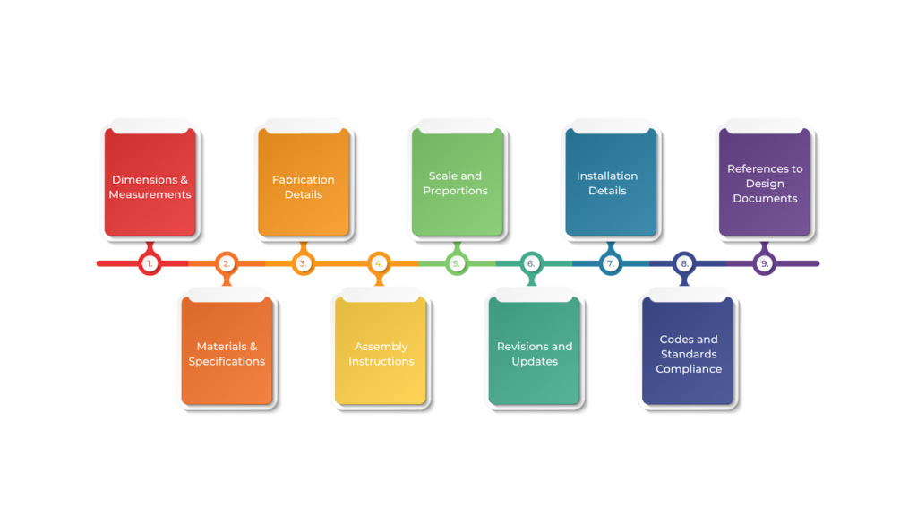
Here are the key components commonly found in shop drawings:
- Dimensions and Measurements
Shop drawings include exact measurements to help builders cut, shape, and assemble parts correctly. Clear dimensions prevent mistakes and ensure everything fits together properly. For instance, if you’re building a steel frame, the drawing will show the exact sizes of beams, columns, and connectors.
- Materials and Specifications
These drawings list the materials needed and any specific details like quality, finish, or strength. This ensures the right materials are used in construction. For example, a drawing for a concrete slab may specify the type of concrete mix, rebar size, and placement.
- Fabrication Details
Shop drawings include instructions on how parts should be made, such as welding, cutting, or assembling. These details help manufacturers create components accurately. For instance, a shop drawing for metal ducts will show how sections should be welded, bent, or fastened together.
- Assembly Instructions
These instructions explain how parts should be assembled on-site, ensuring proper connections and stability. For example, a drawing for a window frame will show how each piece fits, the type of fasteners needed, and the assembly order.
- Scale and Proportions
Drawings are created to scale, meaning they show the size of parts in relation to each other. This helps builders understand how different elements fit together. For example, a section of a building’s wall might be drawn to scale to show the correct placement of windows and doors.
- Revisions and Updates
Changes happen during construction, and shop drawings should reflect updates to prevent mistakes and delays. For instance, if the electrical wiring layout changes, the updated shop drawing will show the new wiring plan and materials needed.
- Installation Details
These details explain how to install parts correctly, including where to place anchors, how to secure pieces, and any required clearances. For instance, for an HVAC system, a shop drawing may show how to position ducts in the ceiling while leaving enough space for maintenance.
- Codes and Standards Compliance
Shop drawings ensure the construction follows safety rules, industry standards, and building codes. For example, a fire-rated door drawing will confirm that the materials meet fire safety regulations.
- References to Design Documents
Shop drawings often include references to original architectural plans to ensure everything aligns correctly. For example, a drawing for an escalator may refer to the building’s floor plan to ensure proper placement.
By including these details, shop drawings provide clear guidance and help the construction team work efficiently and avoid errors. Since different building elements have unique needs, each type of shop drawing is designed for specific materials, systems, or components.
Improve efficiency and accuracy in your projects. Let’s get started today!
BIM ASSOCIATES is your one-stop BIM Solution provider for Revit Architectural and Structural Solutions. They coordinate with your team to develop, record, and streamline the BIM Revit Model, along with the sheets, Bill of Quantities, Bill of Materials, and clash coordination.
Types of Shop Drawings
Shop drawings come in different types, each playing a key role in construction. They include architectural and structural details, as well as mechanical, electrical, and plumbing (MEPF) layouts.
These drawings act as a link between design and actual construction, giving fabricators, contractors, and installers clear instructions to ensure every part fits perfectly into the project.
Below are the main types of shop drawings in a construction project:
| Types | Purpose | Key Details Included |
| Structural Shop Drawings | Show how structural parts (beams, columns, foundations) should be assembled for safety and accuracy. | Types of materials (e.g., steel grades)Welding and bolting detailsPlacement of anchor boltsAssembly instructions |
| Architectural Shop Drawings | Focus on the appearance and design of the building, ensuring finishes match the planned design. | Dimensions and layout of architectural elementsTypes of finishes (e.g., flooring, drywall)Placement and specifications for doors, windows, and other features |
| Mechanical Shop Drawings | Guide the installation of mechanical systems like HVAC, plumbing, and fire protection. | Layouts of pipes and ductworkLocations of equipment (e.g., HVAC units)System flow and pressure detailsInstallation instructions |
| Electrical Shop Drawings | Show the placement of power, lighting, and control systems for safe and efficient wiring. | Wiring diagrams and panel schedulesCircuit breaker ratings and wire sizesLocations of outlets, switches, and lightingConduit routing and connections |
| Plumbing Shop Drawings | Detail the installation of water supply and drainage systems. | Pipe routes and sizesLocations of sinks, toilets, and other fixturesDrainage and venting detailsWater supply connections |
| Fire Protection Shop Drawings | Ensure proper installation of fire safety systems, including sprinklers and alarms. | Sprinkler system layoutFire alarm and detection locationsFirestopping materialsWater flow calculations |
| Civil Shop Drawings | Used for outdoor construction work, such as grading, drainage, roads, and parking areas. | Site grading and elevation detailsDrainage and stormwater managementRoad and parking lot layoutsLandscaping elements |
| Millwork Shop Drawings | Provide details for custom woodwork like cabinets, doors, and trim. | Types of wood and finishesExact measurements for custom woodworkAssembly and installation instructions |
| Steel Shop Drawings | Focus on cutting, welding, and assembling steel structures like beams and columns. | Sizes and shapes of steel componentsWelding and bolting detailsMaterial specificationsAssembly sequence |
| Glass and Glazing Shop Drawings | Cover the installation of glass elements like windows, curtain walls, and storefronts. | Glass specifications (e.g., thickness, coating)Framing and support detailsInstallation methodsSealant and wheather proofing instructions |
Each type of shop drawing serves a specific purpose, ensuring that materials, components, and assemblies are accurately represented before construction begins. However, the effectiveness of these drawings depends on how they are created.
How to Create Shop Drawings?

Creating accurate shop drawings means understanding project needs, following industry standards, and using modern tools like Building Information Modelling (BIM) software.
These drawings are a clear guide for fabricators, contractors, and installers in ensuring every part is built and assembled properly. Well-prepared shop drawings help reduce mistakes, avoid delays, and improve coordination throughout the project.
Below is a step-by-step guide to creating accurate and reliable shop drawings:
- Understand the Project Specifications and Requirements
Before starting the drawings, carefully review the project plans and specifications. Understand what needs to be built, the materials required, and any special design rules. Pay close attention to project-specific guidelines, building codes, and regulations, especially for structural, electrical, or mechanical details.
- Gather Relevant Documents and Information
Collect all important documents that will impact the shop drawings. These may include:
- Architectural drawings
- Structural drawings
- MEP (Mechanical, Electrical, and Plumbing) drawings
- Manufacturer specifications
- Industry standards and codes
- Define the Scope of the Shop Drawings
Identify exactly what needs to be included in the shop drawings and the level of detail required. Shop drawings can cover different areas, such as structural steel details,
HVAC (Heating, Ventilation, and Air Conditioning) layouts, plumbing and piping diagrams, electrical system layouts, and millwork and cabinetry details.
- Choose the Right Software and Tools
Select the best software for creating the shop drawings. Common choices include AutoCAD, Revit, or SolidWorks. Some projects may require BIM (Building Information Modelling) to improve collaboration and visualisation.
- Begin Drawing the Basic Layout
Start by creating a basic layout of the design. Set the correct scale and dimensions and mark the key reference points like walls, columns, or grids. In addition, draw the main components accurately to ensure correct relationships between different parts.
- Add Detailed Specifications
After finalising the layout, add details such as:
- Material types, finishes, and textures
- Connection methods (e.g., bolted or welded)
- Fabrication methods (pre-fabrication or on-site assembly)
- Sizes, shapes, and tolerances of components
- Include Additional Details and Notes
To ensure clarity, include extra details such as enlarged views of complex sections, cross-sections to show internal details or assembly methods, and labels, callouts, and notes for special instructions.
- Review and Verify Measurements
Double-check all dimensions, materials, and installation methods to match the project requirements. Look for any errors or conflicts that could cause problems during construction or fabrication.
- Collaborate with Other Stakeholders
Share the draft shop drawings with architects, engineers, subcontractors, or fabricators for feedback. Their expertise may help identify potential issues or necessary adjustments.
- Revise and Finalise the Drawings
Make the required revisions based on feedback. Ensure the final drawings are clear, accurate, and meet project standards. Get approval from architects, engineers, or other responsible parties before moving forward.
- Submit for Approval
Send the finalised shop drawings for official approval. The project manager, general contractor, or other key stakeholders may need to review and sign off before fabrication or construction begins.
- Distribution and Implementation
After approval, distribute the shop drawings to the fabrication team, contractors, and other relevant parties. These drawings will serve as a guide during manufacturing and construction.
- Monitor and Adjust as Necessary
During fabrication and installation, monitor progress and make updates if needed. If unexpected site conditions arise, revise the shop drawings to reflect necessary changes, ensuring smooth workflow and avoiding errors or delays.
By following this step-by-step approach, shop drawings will provide a reliable and clear guide for constructing or fabricating the project components.
Even with a well-structured process, the quality of shop drawings plays a crucial role in a project’s efficiency and accuracy. Minor improvements in their preparation and presentation can significantly reduce errors and improve collaboration.
Tips to Improve Shop Drawings
Shop drawings connect design and construction, ensuring projects are built correctly and efficiently. But even small mistakes can cause delays and extra costs. By improving the quality of shop drawings, teams can reduce errors, improve clarity, and work together more smoothly.
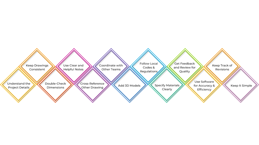
Below are the practical tips to improve shop drawings, making them more precise, efficient, and valuable for construction projects:
- Understand the Project Details
Before making shop drawings, fully understand the project’s scope, design, and requirements. This helps prevent mistakes and ensures your drawings match the architect or engineer’s requirements. Always check the construction documents and ask the design team if anything is unclear.
- Keep Drawings Consistent and Standardised
Consistency makes drawings easier to read, so use standard symbols, lines, and abbreviations for materials and dimensions. Following industry standards, like those from ANSI, helps everyone understand your work without confusion.
- Double-Check Dimensions and Tolerances
Check all dimensions and tolerances carefully before finalising your drawing. Ensure measurements are correct, especially for MEP (mechanical, electrical, plumbing) systems, and follow relevant codes and regulations.
- Use Clear and Helpful Notes
Include simple, clear notes to explain any complex details or special instructions. Notes should highlight important things like material types, finishes, or installation steps to avoid misunderstandings.
- Cross-Reference Other Drawings
When needed, refer to related sections or other drawings, like architectural or structural plans. This helps everyone understand how different parts of the project fit together.
- Coordinate with Other Teams
Ensure your shop drawings align with architectural, structural, and MEP plans. Regularly check with other teams to avoid conflicts and ensure everything fits properly before finalising your work.
- Add 3D Models or Visuals When Required
Include 3D models to show complex details and spatial relationships that may not be clear in 2D drawings. This is especially useful for complicated structures or unusual designs.
- Follow Local Codes and Regulations
Ensure your drawings comply with local building codes and safety standards. This prevents delays or issues with approvals during construction.
- Specify Materials and Products Clearly
List all necessary material details, such as manufacturers, model numbers, and specifications. This avoids confusion when ordering materials and ensures they meet project requirements.
- Get Feedback and Review for Quality
Once your drawings are complete, ask for feedback from engineers or contractors. Peer reviews help catch mistakes early, saving time and money. Also, do a final quality check to ensure accuracy.
- Use Software for Accuracy and Efficiency
Tools like AutoCAD, Revit, or BIM software help create precise drawings. They also offer features like dimensioning, layers, and real-time collaboration to improve efficiency and reduce errors.
- Keep Track of Revisions
Use a clear system for tracking revisions (e.g., “Rev 1,” “Rev 2“) and include dates and change notes. This ensures everyone works with the latest version and prevents mistakes during construction.
- Keep It Simple
Focus on essential details and present them clearly. Avoid clutter so your drawings are easy to follow.
BIM Supports GREEN EARTH.

Conclusion
Shop drawings are crucial for the success of any construction project. These detailed drawings provide clear guidance on how different components will be built and installed, ensuring accuracy in execution.
Reviewing and approving shop drawings before construction starts helps teams work more efficiently, improves coordination, and reduces errors or rework. Ultimately, shop drawings play a vital role in maintaining quality, improving efficiency, and ensuring project success, making them a key tool in modern construction management.
Are you looking for BIM solutions?
BIM ASSOCIATES is your one-stop BIM Solution provider for the Architecture and Structure discipline. Their solutions help clients with better decision-making, cost-saving, efficient construction planning, and green earth initiatives.
You might also like: A Guide to Creating Structural Revit Model in Design Development.
FAQs (Frequently Asked Questions)
1. What is the difference between a working drawing and a shop drawing?
Working drawings provide general construction guidance and help estimate costs. They show the overall design and layout of the project. On the other hand, shop drawings are more detailed and created by contractors, fabricators, or suppliers. These drawings focus on specific components and guide their manufacturing and installation during construction.
2. What is shop drawing in BIM?
In BIM, shop drawings are detailed plans used by contractors and fabricators to build and install different parts of a building. They include precise details such as dimensions, materials, finishes, and how components should be assembled. These drawings are usually created using CAD software.
3. What is the difference between a shop drawing and an as-built drawing?
Shop drawings are made before construction starts and can be modified as needed during the planning stage. As-built drawings, however, are created after the project is completed and show the actual construction details. They cannot be changed unless a renovation or maintenance update is needed.