
Detailed drawings are an essential part of architectural design in the UK,USA and Australia, serving as a guide for transforming ideas into built structures. They go beyond basic layouts by focusing on crucial details such as material specifications, construction methods, dimensions, and connections.
These drawings provide clear, precise information about key building elements like walls, windows, stairs, and custom features. This clarity helps ensure the building is constructed as planned, which reduces errors and simplifies complex parts.
In this article, you’ll explore the role of detailed drawings in architecture, their benefits, various types, key components, and best practices for creating and improving them to enhance design clarity and construction accuracy.
What are Detailed Drawings in Architecture?
Detailed drawings in architecture are scaled visuals that capture specific parts or sections of a building with high precision. These drawings focus on the smaller details, such as materials, exact sizes, connections, and how things are built.
The primary goal of detailed drawings is to make everything clear, reducing confusion and mistakes during construction. These drawings usually have notes, labels, and material details to help builders follow the design correctly.
The clarity provided by detailed drawings is essential for a smooth construction process, but it’s also important to understand how they differ from section drawings.
Comparison of Section and Detailed Drawings
Section drawings and detailed drawings play a crucial role in architectural and construction design by clearly explaining a building’s structure and layout.
Section drawings provide a cut-through view of a building, showing internal elements like walls, floors, and ceilings and how they connect. They help visualise the relationship between different spaces and levels.
Detailed drawings, on the other hand, focus on specific design elements, offering a closer view of intricate components like doors, windows, joints, and materials. These drawings ensure precision and clarity in construction.
Both types of drawings are essential for maintaining accuracy, improving communication, and ensuring proper execution in construction. They help builders and contractors understand design details and technical requirements. Understanding their differences highlights their unique contributions to the building process.
Below are the key differences between section and detailed drawings:
| Aspects | Section Drawings | Detailed Drawings |
| Purpose | To show a cut-through view of a building or structure, revealing internal elements, connections and relationships. | To provide a close-up view of specific parts or components with intricate details and joints.. |
| Scope | Covers larger areas or multiple levels of a building, showing the overall structure. | Focuses on specific parts or assemblies, such as doors, windows, or connections and joints. |
| Level of Detail | Provides moderate detail of elements like walls, floors, and structural components. | Provides high levels of detail, including materials, finishes, and dimensions of individual components. |
| Scale | Often drawn at a smaller scale to capture the overall context of the building. | Typically drawn at a larger scale to clearly show small, intricate features. |
| Use in Construction | Helps to understand the vertical relationships and layout of a building, particularly for construction sequencing. | Used for precise construction or fabrication, guiding contractors and builders on the exact specifications. |
| Perspective | Provides a view from a “cut” through the building, often showing both interior and exterior features. | Presents a magnified view, focusing on a specific construction detail, often without the context of the broader structure. |
| Typical Content | Structural elements, rooms, and spaces in relation to one another (e.g., ceiling heights, floor slabs). | Specific building elements such as joints, connections, window frames, and finishes. |
Section drawings provide a detailed, cut-through view of a building’s structure, offering insight into the vertical relationships between different levels and components, while detailed drawings focus on the specifics of how those components will be constructed.
These detailed drawings make the design clearer and help avoid mistakes during construction. With their exact details, they offer key benefits during both the design and building stages.
Benefits of Detailed Drawings
Detailed drawings are a valuable tool in architecture, providing specific information that helps make sure the design is built as planned. They provide precise information on every design aspect, from materials to measurements.
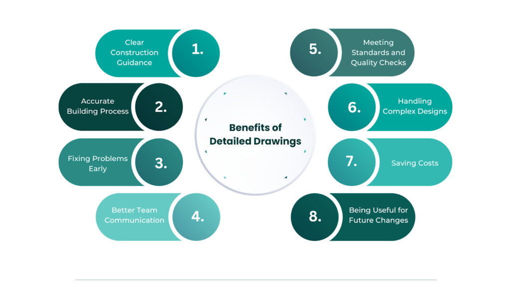
These drawings offer several key benefits that help ensure a successful construction project, such as:
- Clear Construction Guidance: Detailed drawings give exact instructions for materials, sizes, and how things should be built. This reduces confusion and helps builders understand the plan better.
- Accurate Building Process: These drawings ensure precise construction by showing scaled, detailed visuals that builders can follow step by step, leading to fewer errors.
- Fixing Problems Early: Detailed drawings focus on every part of the design and help identify issues, such as structural conflicts or material mismatches before construction begins. This helps prevent costly changes later.
- Better Team Communication: Detailed drawings act as a common reference for architects, engineers, and contractors, helping everyone work together smoothly and stay aligned.
- Meeting Standards and Quality Checks: These drawings ensure the building follows local codes and act as an inspection guide to confirm everything is done properly.
- Handling Complex Designs: For unique or intricate features, detailed drawings provide the level of detail needed to turn creative ideas into practical, buildable plans.
- Saving Costs: Detailed drawings reduce mistakes and rework, saving time and money. They also allow for more accurate material estimates, reduce waste, and help keep the project within budget.
- Being Useful for Future Changes: Detailed drawings serve as a valuable reference for renovations or repairs, providing an understanding of the building’s structure over time.
Detailed drawings offer many benefits, from improving accuracy to simplifying communication among project teams. Their ability to break down complex elements into precise instructions is crucial in architecture. To understand how these benefits are applied in practice, it’s helpful to look at the different types of detailed drawings used in architecture.
Also read: Importance of Construction Drawings: Types, Details & Regulations.
Types of Detailed Drawings in Architecture
Detailed drawings come in various types, each serving a specific purpose in the construction process. Understanding the different types of detailed drawings is essential for ensuring that every part of the design is executed correctly.
Some of the most common types of detailed drawings in architecture are as follows:
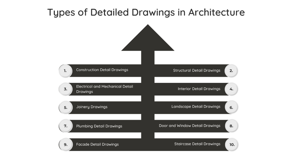
1. Construction Detail Drawings
Construction detail drawings show specific building parts, like walls, windows, doors, structural components and roofs, with detailed instructions on how to build them. They include measurements, materials, and connection details to ensure everything is made as planned.
2. Structural Detail Drawings
Structural detail drawings focus on the building’s structural elements, such as beams, columns, foundations, rebaring, connections, joints, assembly and load-bearing walls. They provide details about sizes, materials, reinforcements, and connections to ensure the structure is safe and strong.
3. Electrical and Mechanical Detail Drawings
Electrical and mechanical detail drawings show the layouts for systems such as wiring, plumbing, HVAC, and other utilities. They ensure these systems fit well with the building, work properly, and meet safety standards.
4. Interior Detail Drawings
Interior detail drawings focus on detailed interior features like cabinets, floors, moldings, and decorative details. They include exact measurements and materials to ensure custom interior elements are made and installed properly.
5. Joinery Drawings
Joinery drawings show how wooden parts, such as doors, windows, stairs, and cabinets, are assembled. They provide precise dimensions, materials, and construction methods to ensure the woodwork fits perfectly into the design.
6. Landscape Detail Drawings
Landscape detail drawings focus on outdoor features like gardens, pathways, retaining walls, water features, and other landscaping elements. They include details about materials, plants, and how the outdoor design connects with the building.
7. Plumbing Detail Drawings
Plumbing detail drawings show the layout of water pipes, drainage systems, and fixtures in a building. They include exact pipe sizes, materials, and connection points to ensure the plumbing is installed correctly and works properly.
8. Door and Window Detail Drawings
Door and window detail drawings focus on the details of doors and windows, including their sizes, materials, hardware, and how they should be installed. They ensure doors and windows fit perfectly into the building’s design and structure.
9. Facade Detail Drawings
Facade detail drawings show the design and construction of a building’s exterior. They include details about cladding, windows, doors, and other features, as well as the materials, finishes, and how everything fits together structurally.
10. Staircase Detail Drawings
Staircase detail drawings show the design and construction of stairs, including the steps, handrails, and supports. They ensure the stairs are safe, functional, and comply with building codes. Mould drawings for casting concrete stairs are made in Revit.
Each type of detailed drawing is important for ensuring the design is accurately built, reducing errors, and maintaining quality. To achieve this, it’s essential to understand the different parts of these detailed drawings.
Start simplifying your projects and unfolding these benefits today!
BIM ASSOCIATES is your one-stop BIM Solution provider for Revit Architectural and Structural Solutions. They coordinate with your team to develop, record, and streamline the BIM Revit Model, along with the sheets, Bill of Quantities, Bill of Materials, and clash coordination.
Components of Detailed Drawings
Detailed drawings in architecture consist of several key components that work together to ensure accurate construction, clarity, and effective communication of design concepts. These components deliver essential information to builders, contractors, and engineers, helping them execute the design correctly.
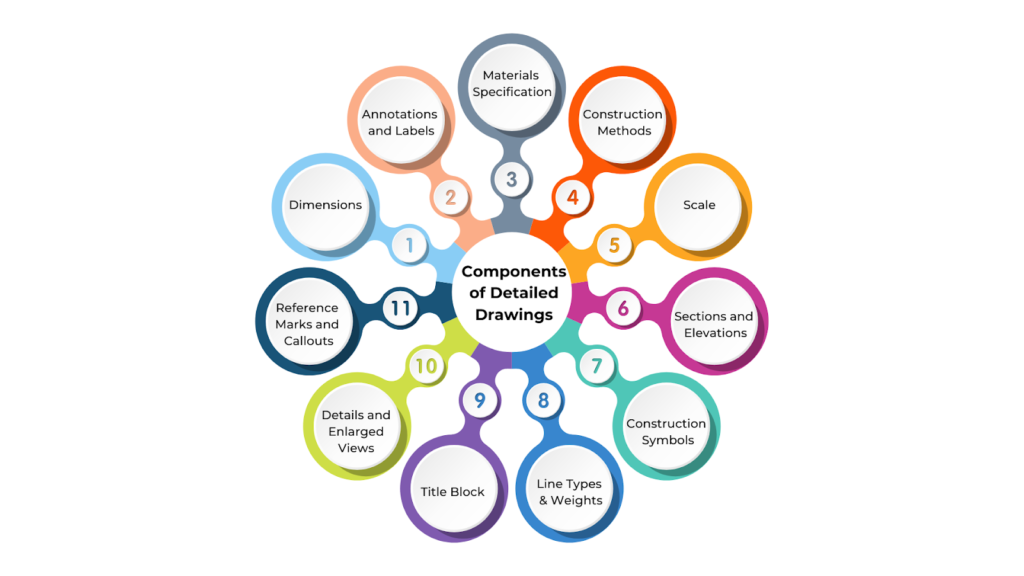
The primary components of detailed drawings are as follows:
1. Dimensions
Dimensions are important in detailed drawings because they show the exact measurements for every part of the design, including lengths, widths, heights, and distances between elements. Accurate dimensions ensure everything fits together correctly during construction.
2. Annotations and Labels
Annotations are notes or text that explain specific parts of the drawing. They provide extra details about materials, finishes, or how things should be built. These labels help avoid confusion and ensure everything is clearly understood during construction.
3. Materials Specifications
Detailed drawings often include information about the materials for each part of the design. This can include the type of material (such as brick, wood, or steel), its quality and finish, and any special installation requirements. Clear material specifications help the construction team choose the right materials for each part.
4. Construction Methods
Detailed drawings may include instructions on how to build certain parts of the structure. These details explain how pieces should be joined or fastened, the steps for installation, and any temporary supports needed during construction. These methods ensure the building is safe and built following the best practices.
5. Scale
All detailed drawings are made to a specific scale, usually larger than the main floor plans or elevations. For example, common scales like 1:10 or 1:20 help show fine details clearly and accurately. The scale ensures that all measurements are consistent and proportional.
6. Sections and Elevations
Detailed drawings often include sections and elevations to show different views of the building. Sections show a vertical slice of the structure, revealing how parts like walls, floors, and foundations fit together. Elevations provide an outside view of the building, showing how features like windows, doors, and outer surfaces are arranged.
7. Construction Symbols
Symbols in detailed drawings represent common construction parts, such as doors, windows, fixtures, electrical outlets, and plumbing components. These symbols follow standard rules, making it easier for contractors and engineers to understand the drawings without much explanation.
8. Line Types and Weights
In detailed drawings, different types of lines are used to show various parts of the design:
- Thick lines show visible edges or parts that are being cut through.
- Dashed lines represent hidden elements, like internal structures or beams above.
- Thin lines are used for less important details, such as background information or measurement lines.
9. Title Block
The title block is usually located in the corner of the drawing. It includes important details about the project, such as the project name, drawing title, drawing number, scale, date, the architect or designer’s name, and any changes made to the drawing. This information helps identify the drawing and ensures it is appropriately used in the project documents.
10. Details and Enlarged Views
Sometimes, detailed drawings show larger views of specific parts, like door frames or window installations. These views allow for a closer look at the details of certain parts that require more explanation than the main drawing.
11. Reference Marks and Callouts
Reference marks and callouts point out specific drawing areas or connect different design parts. They help identify extra details and ensure the correct elements are linked throughout the project’s documents.
Understanding the components of detailed drawings is key to creating accurate architectural plans. These elements work together to ensure precision, but making a detailed drawing involves careful planning and execution.
Creating a Detailed Drawing in Architecture
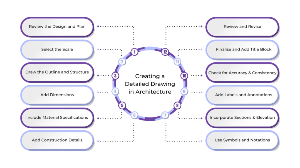
Creating a detailed drawing in architecture involves translating design ideas into precise, technical visuals that guide the construction process. These drawings include specific measurements, materials, and construction details to ensure accuracy and clarity. A well-crafted detailed drawing is essential for turning a design concept into a successful finished structure.
Below is a step-by-step guide on how to create a detailed drawing:
1. Review the Design and Plan
Before starting the detailed drawing, carefully review the overall design or floor plans. Identify the parts that need more detail, such as windows, doors, stairs, or custom features. This will help you focus on areas that require exact measurements and specifications.
2. Select the Scale
Choose the right scale for the drawing. Detailed drawings are usually drawn at a larger scale (like 1:10 or 1:20) than general plans to show small features clearly. Pick a scale based on the size and complexity of the part you’re detailing.
3. Draw the Outline and Structure
Begin by drawing the basic outline of the part or section you’re detailing. Start with the main structure, such as the walls, columns, or beams. This will set the foundation for adding more detailed elements later.
4. Add Dimensions
Accurate dimensions are essential in detailed drawings. Measure and mark the exact lengths, widths, heights, and distances of all elements. Include dimensions like door and window openings, distances between structural parts, and material thicknesses. Use the same style for dimensions throughout the drawing to keep it clear.
5. Include Material Specifications
List the materials that will be used for each part of the drawing, like wood, steel, concrete, or glass. Label the materials and finishes directly on the drawing so that everyone involved in construction knows what materials are needed.
6. Add Construction Details
Include details on how the parts of the structure will be connected or assembled, such as how beams are joined, walls are anchored, or windows and doors are framed. These details will guide the builder in putting everything together.
7. Use Symbols and Notations
Use standard symbols for common elements like doors, windows, stairs, electrical outlets, and plumbing fixtures. These symbols help keep the drawing easy to understand for professionals working on the project.
8. Incorporate Sections and Elevations
If needed, add sections or elevations to show a cut-through view of the component. These views help show how elements, like wall sections or structural layers, fit together vertically. They also help give context and show how materials and parts align.
9. Add Labels and Annotations
Label important parts of the drawing to provide clear details about materials, finishes, and construction methods. Use short notes (annotations) to explain any special instructions or highlight important details that must be followed during construction. Keep the annotations simple and easy to understand.
10. Check for Accuracy and Consistency
After completing the drawing, carefully check all measurements, materials, and construction details to ensure they are correct. Ensure the drawing matches the overall design and includes all necessary information. This step is essential to avoid mistakes during construction.
11. Finalise and Add Title Block
Once you’re happy with the drawing, add a title block with key details, like the drawing title, scale, project name, date, and drawing number. The title block helps identify and record the drawing correctly in the project files.
12. Review and Revise
Before finalising the drawing, review it to ensure it’s clear and complete. Then, allow an engineer or contractor to check it to ensure all the necessary details are present and it’s easy to understand. Based on their feedback, make any needed changes.
By following these steps, you ensure that every part of the design is clearly shown, giving builders the information they need to build the structure as planned.
However, even the most carefully made detailed drawing can be improved. Updating and refining it keeps the drawing clear, accurate, and effective in showing the design plan.
Improving a Detailed Drawing in Architecture
Improving a detailed drawing is essential to ensure it communicates the design, reduces construction mistakes, and serves as a practical guide for builders and contractors. Regular updates help align the drawing with project goals and ensure it remains a reliable tool throughout construction.
Some of the effective ways to improve detailed drawings in architecture are as follows:
Use Consistent Line Weights and Styles
Make sure the lines in the drawing are consistent. Use thick lines for important parts like walls and beams and thinner lines for smaller details. Different line styles, like solid, dashed, or dotted, can help show what’s visible and hidden, making the drawing easier to understand.
Clarify Dimensions and Scale
Double-check all dimensions and place them in clear spots to avoid clutter. Use a simple, standard measurement system to make it easy to read. Also, use a larger scale for small details and a smaller scale for bigger areas.
Include Detailed Materials Specifications
Clearly show what materials are used for each design part, like wall finishes or structural materials. Label them with the right specifications (e.g., concrete type, wood, or insulation) to avoid confusion and ensure the right materials are used in construction. In addition, include extra details like texture, colour, or finish to help explain the design.
Improve Annotations and Labels
Annotations add an extra explanation, so ensure they are clear, brief, and consistent. Don’t overcrowd the drawing with too much text, but include enough to highlight important parts or instructions. Use callouts to point to specific areas or extra details, like construction notes or material information.
Use Sections and Enlarged Views
Sections help show how parts fit together vertically, giving builders a better idea of how to build it. You can also break the complex details into smaller sections or enlarged views. For example, a window detail might be shown in a larger view to show small parts like the frame and glazing.
Simplify Where Possible
Remove unnecessary parts or simplify tough sections to keep the drawing clean and readable. This could mean removing extra decorative details or using references to other drawings instead of adding too many dimensions.
Double-Check for Accuracy
Check that all dimensions, materials, and construction methods are correct and match the other project documents. Then, compare the drawing with the floor plan, elevation, and structural drawings to check for mistakes.
Ensure Clear Hierarchy and Organisation
Organise the drawing in a way that’s easy to follow. Group similar parts together and make sure the most important elements stand out. Use labels and reference marks to guide the viewer’s eye and help them understand complex details.
Incorporate Feedback from Others
Ask for feedback from colleagues, like structural engineers, contractors, or other architects, to ensure the drawing is clear, accurate, and practical. Getting different viewpoints can help spot areas that need more explanation or improvement, making the drawing as effective as possible.
Improve Digital Tools and Technology Use
Use CAD software (e.g., AutoCAD, Revit) and BIM (Building Information Modelling) to create more precise and detailed drawings. These tools allow for real-time updates, easy scaling, and better visualisation of complex details. They can also automatically update other related drawings when changes are made, ensuring everything stays consistent.
Ensure Compatibility with Construction Workflow
Think about how the drawing will be used during construction. Ensure all the information is easy for workers to understand and use on-site. Avoid technical terms or unclear symbols that could slow things down or cause confusion.
Check for Regulatory Compliance
Make sure the drawing meets local building codes and rules. This could include requirements for structure, fire safety, accessibility, and other legal standards. Adding notes about compliance or referencing the relevant codes ensures the design follows the rules and helps avoid delays or problems during construction.
Using the above strategies can make your detailed drawings clearer, more accurate, and more effective. These improvements help avoid construction mistakes, simplify the building process, and ensure the design is executed accurately.
BIM Supports GREEN EARTH.

Conclusion
Detailed design drawings are essential for the success of any architectural project. They provide the accuracy and clarity to turn design ideas into real structures. These drawings ensure that every part of the project, from structural components to fine details, is understood and built as planned.
By removing confusion and addressing every detail, detailed drawings help avoid mistakes, reduce delays, and ensure the finished building matches the original design vision.
Are you looking for BIM solutions?
BIM ASSOCIATES is your one-stop BIM Solution provider for the Architecture and Structure discipline. Their solutions help clients with better decision-making, cost-saving, efficient construction planning, and green earth initiatives.
You might also like: Understanding Concrete Frame Structures: Types & Components.
FAQs (Frequently Asked Questions)
1. What are detailed drawings?
Detailed drawings are clear and accurate representations of a part’s size, shape, and how it should be made. They focus only on the information needed to create the part.
2. What do detailed drawings show?
Detailed drawings show the design clearly, including measurements, materials, and finishes. They help ensure the project is built according to the specifications and the owner’s expectations.
3. What are standard detail drawings?
Standard detail drawings are ready-made templates with common notes and details. They are used in construction design to save time and simplify the process.