Research shows that design changes in the construction industry contribute to 56.5% of cost overruns and 40% of project delays, often due to a lack of clarity or incomplete planning. This shows why architectural drawings are important and help reduce these issues by turning design ideas into clear, buildable plans. Beyond their aesthetic value, these drawings ensure functionality, structural stability, and compliance with regulations, helping to prevent costly mistakes and delays.
Architectural drawings help architects, engineers, and builders stay aligned throughout construction by providing clear and precise details of a building’s components.
In this article, you’ll learn about architectural drawings and their crucial role in design. In addition, you’ll discover the different types of architectural drawings, the best software for architectural drawing, and various techniques and methodologies used in the field.
What are Architectural Drawings?
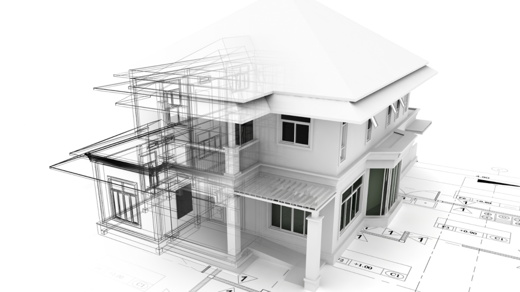
Architectural drawings are detailed plans that show a building’s design, layout, and construction details. They act as a visual guide for architects, engineers, and builders, helping ensure the design is accurately followed while meeting structural and regulatory requirements.
Unlike building drawings, which focus more on the physical structure and construction aspects (like structural framing and electrical systems), architectural drawings emphasise the aesthetic design, spatial arrangement, and functionality of spaces within the building.
These drawings include site plans, floor plans, elevations, sections, and detailed views. In addition, they show dimensions, materials, and construction methods to ensure clear communication of the design.
Architectural drawings are essential for project planning, cost estimation, and team coordination. They are a key part of the construction and design process because of the following reasons:
- Visual Representation: Architectural drawings show a clear and detailed image of how a building will look, including its design, layout, and structure. This helps stakeholders to understand the final project.
- Construction Guide: These drawings guide builders, engineers, and contractors, ensuring every part of the building is constructed as planned. They include essential details like dimensions, materials, and construction methods.
- Regulatory Compliance: Architectural plans must follow local building codes and safety rules to get permits. This ensures the building is safe and legally approved.
- Cost Estimation: By listing materials, labour, and other details, architectural drawings help calculate the project’s total cost, assisting in budget planning and avoiding overspending.
- Coordination & Collaboration: Since construction involves many professionals, like engineers and designers, architectural drawings are a reference point for improving communication and reducing conflicts.
- Client Approval: Clients review the architectural drawings to ensure the design meets their expectations before construction begins. This helps avoid misunderstandings and allows for changes if needed.
- Problem Identification: Architectural drawings help spot potential problems or design flaws early on, preventing costly mistakes and delays.
- Legal Documentation: These drawings are used to get construction permits, sign contracts, and resolve disputes. They provide an official record of the building’s design and legal compliance.
- Future Reference: After the project is finished, architectural drawings can be used for maintenance, renovations, or expansions, ensuring any future changes stay consistent with the original design.
Architectural drawings provide the visual framework for a building’s design, but to bring that vision to life, it’s essential to understand how the structure will support it. Architectural and structural drawings are critical to construction but serve distinct roles.
Differences Between Architectural and Structural Drawings
Architectural drawings focus on the design and layout of the building, while structural drawings ensure the building’s stability and follow engineering principles. Understanding the differences helps architects, engineers, and contractors work together for successful project completion.
Below is an overview of the differences between architectural and structural drawings:
| Aspects | Architectural Drawings | Structural Drawings |
| Definition | Illustrate the design, spatial layout, and aesthetics of a building. | Focus on the structural integrity, structural components and related connections and details load-bearing components of a building. |
| Purpose | Provide a visual representation of the building’s design, layout, and materials. | Ensure the building can withstand loads, forces, calculate Bill of Material, Bill of Quantities and environmental factors. |
| Prepared By | Architects prepare these drawings. | Structural engineers prepare these drawings. |
| Key Focus | Floor plans, elevations, sections, doors, windows, and interior spaces. | Beams, columns, structural floor plans, foundations types and plans, slabs, load distribution, and reinforcements. |
| Materials Covered | Finishing materials like flooring, paint, tiles, and decorative elements. | Concrete, steel, wood, and reinforcement details. |
| Compliance | Ensures design feasibility, aesthetics, and adherence to building codes. | Ensures structural safety, strength, and stability per engineering standards. |
| Technical Complexity | Focuses more on layout, space planning, and user experience. | Highly technical with precise calculations and reinforcement details. |
| Usage in Construction | Architects, contractors, and interior designers use it to guide the overall construction. | Structural engineers and contractors use it for material procurement, estimation, load-bearing and stability considerations. |
| Modification Flexibility | More flexible, allowing design changes based on client requirements. | Limited flexibility due to strict engineering constraints. |
Architectural and structural drawings have different roles, but both are important for designing and building a structure. Architectural drawings especially guide the design process, from the first ideas to the final construction.
Importance of Architectural Drawing in the Design Process
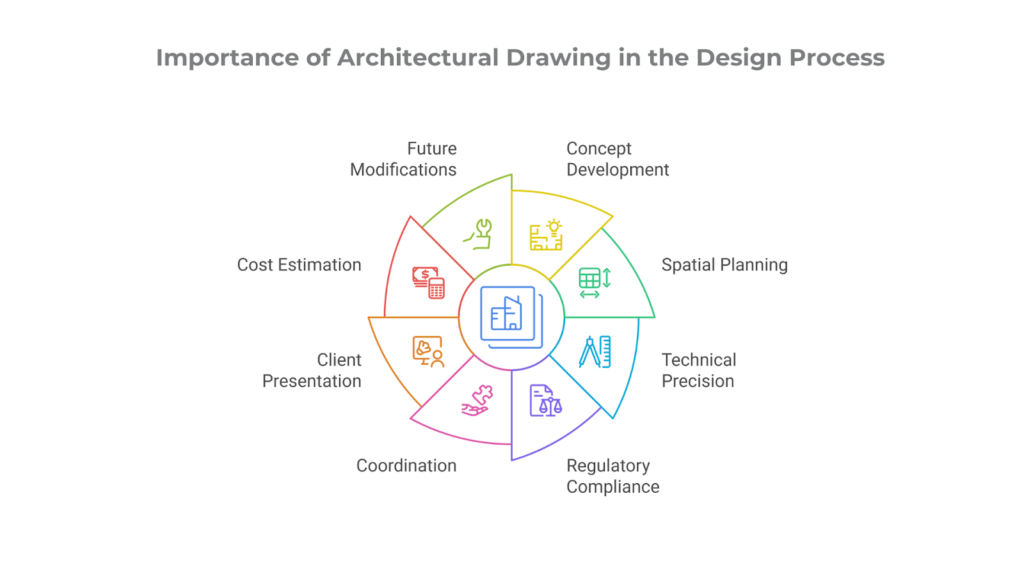
Architectural drawings are a key part of the design process. They help architects share their ideas and technical details, from early sketches to final construction plans. These drawings turn creative ideas into real, functional buildings.
Architectural drawings guide decision-making, ensure regulatory compliance, and facilitate collaboration among clients, engineers, and construction teams. Below is an overview of how these drawings play an important role in the design process:
Concept Development & Ideation
Architectural drawings help turn design ideas into pictures, allowing architects to test different layouts and how spaces fit together. Early sketches and diagrams help refine the design before planning in more detail.
Spatial Planning & Layout Design
Floor plans and site layouts show how rooms and spaces are arranged, how people will move around, and any zoning rules. They ensure space is used well while following building regulations and providing a good user experience.
Technical Precision & Construction Documentation
Detailed drawings provide measurements, materials, and structural details to guide construction. Elevations, sections, and detailed views help contractors understand the project clearly and ensure safety standards are met.
Regulatory Compliance & Permit Approvals
Architectural drawings are used to get planning approvals and building permits. They show that the design follows zoning laws, safety codes, and building regulations and includes the technical information needed for legal documents and environmental certifications.
Coordination & Collaboration with Other Disciplines
Architectural drawings also include systems like plumbing, electrical, and heating. This helps prevent design problems and errors during construction, as everyone works from the same plan.
Client Presentation & Visualisation
3D models and rendered drawings help clients see how the finished project will look, including materials, lighting, and how spaces are arranged. This helps them make informed decisions about changes and material choices.
Cost Estimation & Material Planning
Drawings help estimate costs by listing materials, labor, and structural needs. Contractors use these details to create budgets, schedules, and timelines for the project.
Future Maintenance & Modifications
As-built drawings show how the building was actually built, making it easier for future repairs, renovations, or system upgrades. Maintenance teams use these drawings to find electrical circuits, plumbing, and other vital parts.
To ensure the design and construction are shown correctly, it’s essential to know the different types of architectural drawings and the key details they should have.
Ready to improve precision and simplify your design process?
BIM ASSOCIATES is your one-stop BIM Solution provider for Revit Architectural and Structural Solutions. They coordinate with your team to develop, record, and streamline the BIM Revit Model, along with the sheets, Bill of Quantities, Bill of Materials, and clash coordination.
Types of Architectural Drawings & Key Details to Include In Your Design Process
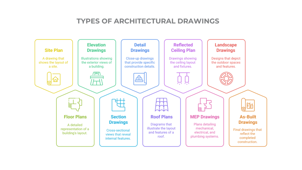
Architectural drawings offer detailed information on layouts, room sizes, materials, and basic structure, furnitures, ensuring clarity and accuracy throughout the project. Each type of drawing serves a specific purpose, and understanding these roles and key details helps architects, engineers, and builders turn design ideas into practical, functional buildings.
The main types of architectural drawings and the key details to include are as follows:
1. Site Plan Drawings
Site plans outline the layout of a project within its surrounding environment. It provides an aerial view of the site, showing how the building fits with the landscape and infrastructure. This plan ensures proper zoning, accessibility, and environmental considerations are addressed. The key details include:
- Property boundaries and setback lines.
- Centre line of all structural components.
- Location of buildings, roads, parking, and landscaping.
- Entry and exit points, pathways, and site circulation.
- Topography, contour lines, and drainage systems.
- Utility connections (water, electricity, sewage).
- Scale, north arrow, and legend.
2. Floor Plans
Floor plans provide a top-down view of a building’s layout that outlines room arrangements, flow, and spatial connections. It is a key reference for interior planning, ensuring the design is functional, efficient, and meets building code requirements. The key details include:
- Room layout with names and functions.
- Door and window placements with dimensions.
- Wall thickness and partition locations.
- Built-in furniture and appliances.
- Staircases, lifts, and accessibility routes.
- Floor level and elevation markers.
3. Elevation Drawings
Elevations are flat views of a building’s exterior that clearly show the height, facade design, and material finishes. These drawings help visualise the building’s appearance from various angles, ensuring it meets aesthetic goals and regulatory standards. The key details include:
- Front, rear, and side views of the building.
- Roof design and parapet details.
- Windows, doors, balconies, and facade treatments.
- Exterior finishes, materials, and textures.
- Overall height and relationship to the ground level.
4. Section Drawings
A section drawing offers a cut-through view of the building, showing internal construction, structural elements, and the distribution of vertical space. It helps architects and engineers understand the building’s layers, materials, and how floors are connected, helping them make more effective planning and execution. The key details include:
- Structural elements like beams, columns, and slabs.
- Floor-to-ceiling heights and levels.
- Staircases, wall thickness, and insulation details.
- Roofing, foundation, and material layers.
- Relationship between different floors and spaces.
5. Detail Drawings
Detail drawings focus on specific construction elements, providing clear and precise instructions for builders and fabricators. These drawings highlight intricate features, like staircases and joinery, ensuring accurate execution. The key details include:
- Staircases, door/window joinery, and railing details.
- Wall sections with insulation and cladding specifications.
- Material layers and finishes.
- Structural reinforcements and fixings.
- Expansion joints and waterproofing elements.
6. Roof Plans
A roof plan shows the layout, slopes, and structural components of a building’s roof that ensures proper drainage and stability. It also includes details on ventilation, insulation, and mechanical elements that support the roof’s overall functionality. The key details include:
- Roof slopes, ridges, and valleys.
- Material specifications and insulation layers.
- Drainage points, gutters, and downspouts.
- Roof openings, skylights, and ventilation systems.
7. Reflected Ceiling Plan (RCP)
An RCP offers a top-down ceiling view, showing lighting, mechanical, and structural elements. It ensures proper placement of fixtures and alignment with the floor plan for a cohesive design. The key details include:
- Ceiling height, type and surface treatments.
- Light fixtures, fans, and air vents.
- HVAC diffusers, fire alarms, and sprinkler systems.
- Structural ceiling elements like beams, maintenance ducts. .
8. MEPF Drawings (Mechanical, Electrical, Plumbing, Fire)
MEPF drawings outline the utility systems required for a building’s operation, ensuring efficiency and safety. They guide contractors in precisely installing essential infrastructure, such as plumbing, wiring, and ventilation. The key details include:
- Plumbing layouts for water supply and drainage.
- Electrical wiring, outlets, and switch locations.
- HVAC (Heating, Ventilation, and Air Conditioning) ductwork.
- Fire suppression and safety systems.
9. Landscape Drawings
Landscape drawings depict the outdoor spaces around a building that ensures a smooth blend of natural and built elements. These plans include gardens, pathways, and hardscape features to create aesthetic appeal and environmental balance. The key details include:
- Trees, plants, and softscape elements.
- Pathways, hardscapes, and outdoor seating.
- Fences, lighting, and irrigation systems.
- Relationship between landscaping and built structures.
10. As-Built Drawings
As-built drawings reflect the final, constructed version of a building, including any changes made during construction. They record the completed structure accurately and support maintenance, renovations, and future expansions. The key details include:
- Actual dimensions, material modifications, and adjustments.
- Final placements of mechanical and electrical systems.
- Differences from original architectural plans.
- Reference points for future maintenance or renovations.
Understanding the different types of architectural drawings allows you to create accurate and effective designs. However, the right software is crucial for bringing these drawings to life with precision and efficiency.
Also read: Importance of Construction Drawings: Types, Details & Regulations.
Best Software for Architectural Drawings
In the past, architects used pencils, pens, rulers, compasses, and tracing paper to make their drawings. These tools needed skill and careful attention, with different pencils and pens for different line thicknesses and textures.
Currently, architectural drawings need both traditional tools and modern digital software to ensure accuracy, clarity, and efficiency in the design process. Using the right software helps improve workflow, promotes teamwork, and allows architects to turn ideas into detailed plans ready for construction.
Below is an overview of the software required for architectural drawings:

Computer-Aided Design (CAD) Software
CAD software is crucial for creating detailed 2D and 3D architectural drawings. These programmes help architects draft floor plans, elevations, and sections precisely. Famous CAD software includes:
- AutoCAD: A widely used CAD tool that enables architects to create precise 2D & 3D drawings with advanced tools and layer management.
- ArchiCAD: A popular BIM-integrated CAD software ideal for designing complex architectural models with parametric objects.
- MicroStation: A CAD software designed for infrastructure and large-scale architectural projects that offers advanced modelling capabilities.
Building Information Modelling (BIM) Software
BIM software goes beyond traditional CAD by incorporating real-world construction data. It allows architects to visualise and simulate building performance. Popular BIM software includes:
- Revit: A top BIM software by Autodesk that creates intelligent 3D models, including data on materials, costs, and structural integrity.
- Vectorworks Architect: A versatile BIM tool that supports 2D drafting and 3D modelling, featuring an easy-to-use design interface.
- BricsCAD BIM: A cost-effective alternative to Revit that provides similar BIM features for architects and engineers.
3D Modelling & Rendering Software
These programs assist architects in visualising and presenting their designs in a more immersive and realistic way. Popular 3d modelling and rendering software includes:
- SketchUp: A user-friendly 3D modelling software perfect for conceptual design and quick architectural sketches.
- Rhino 3D: Known for its flexibility, this software is used for complex modelling, particularly parametric architecture.
- Blender: A free, open-source 3D modelling and rendering software commonly used for architectural visualisation and animation.
- Lumion: A real-time rendering software that enables architects to create photorealistic images & animations of their projects.
Graphic Design & Presentation Software
This software helps architects improve their drawings and create engaging presentations for clients and stakeholders. Popular graphic design & presentation software includes:
- Adobe Photoshop: Used for post-processing architectural renderings and refining presentation boards.
- Adobe Illustrator: Ideal for creating vector-based diagrams, site plans, and polished architectural graphics.
- InDesign: Used for assembling architectural portfolios and designing presentation layouts.
Structural & Analysis Software
This software is crucial for ensuring the stability, durability, and safety of architectural designs. Popular structural & analysis software includes:
- Tekla Structures: A BIM software for a structural design that provides tools for steel detailing and concrete modelling.
- STAAD.Pro: Used for structural analysis and simulation to assess the strength and integrity of building materials.
- ETABS: A specialised software for structural analysis & design that focuses on the seismic & effective performance of buildings
Concept Sketching & Digital Drawing Software
This software is ideal for architects who enjoy digital hand sketching and seek a natural, intuitive drawing experience. Popular concept sketching & digital drawing software includes:
- Procreate: A versatile drawing app for iPads that is perfect for quick architectural sketches.
- Morpholio Trace: A sketching app that lets architects overlay and refine their concepts digitally.
- Concepts App: A flexible, vector-based sketching tool ideal for ideation and rough design drafts.
The choice of tools in architectural drawing depends on the project stage, the specific needs of the drawing, and the architect’s or designer’s preferences.
Each tool has its benefits, from the hands-on feel of traditional drawing to the flexibility and speed of digital tools. Alongside the tools, the techniques employed in the process also play a critical role in shaping the design.
Drawing Techniques and Methodologies in Architecture
Architectural drawing techniques are important for turning design ideas into accurate, buildable plans. Architects use different methods, from rough sketches to detailed construction drawings, to share their ideas clearly.
These techniques show how spaces are arranged, what materials will be used, & how the design will function. Each method and technique plays a specific role in designing, visualising, and building, ensuring everything flows smoothly from the idea stage to completion.
Below is an overview of the different drawing techniques & methodologies used in architecture:
| Techniques & Methodologies | Key Details |
| Freehand Sketching | Used in the early design stages to explore ideas quickly before moving to technical drawings, helping architects visualise space and shapes. |
| Orthographic Projection | A 2D representation of buildings from different angles, including floor plans, elevations, and sections, essential for creating accurate construction documents. |
| Isometric & Axonometric Drawing | Provides a 3D view without distortion, making them ideal for technical drawings, exploded views, and modular or prefabricated designs. |
| Perspective Drawing | Adds depth using one-, two-, or three-point perspectives, making them useful for client presentations and visual storytelling. |
| Rendering & Visualisation | Improve drawings with shading, textures, and lighting effects, making them lifelike for presentations, marketing, and design approvals. |
| Sectional & Cutaway Drawings | Reveal a building’s interior by cutting through it, exposing walls, floors, and materials essential for structural planning and coordination. |
| Detail Drawings | Focus on small construction elements like stairs, windows, and material joins, using larger scales to ensure accurate fabrication. |
| Presentation & Diagrammatic Drawings | Uses exploded views, diagrams, and storytelling to present design ideas effectively in client pitches and competitions. |
| Hand-Drawn vs. Digital Drawing | Hand drawing is great for brainstorming, while digital tools offer precision and speed, with many architects combining both methods. |
| Parametric & Computational Design | Uses math and automation to create complex, innovative structures, such as responsive facades and futuristic architecture. |
| Layering & Line Weights | Varying line thicknesses differentiate building elements, with thicker lines focusing on main structures and thinner lines showing finer details. |
| Scale & Proportion | Scaling ensures accurate representation of real-world sizes, using ratios like 1:50, 1:100, or 1:200 for floor plans and 1:10 or 1:5 for details. |
The techniques and methodologies used in architectural drawings help to clearly communicate complex design ideas, but it’s the labelling and annotation that truly ensure the details are understood.
Labelling & Annotation in Technical Drawings
Technical drawings act as blueprints in architecture, showing everything from electrical layouts to plumbing and the materials used. Additionally, they serve as a detailed record of the building’s inner structure, which is helpful for future maintenance or repairs.
In architecture and design, labelling and annotations help share key information in architectural drawings. For instance, a simple line in a drawing represents something important, such as a wall or a window.
Labelling and annotations provide detailed information about the size, materials, and direction of the architectural elements. This ensures everyone, from the architect to the construction workers, understands the design clearly and avoids mistakes. Here are some of the tips for labelling and annotations:
- Mark all parts like walls, doors, and windows properly to prevent confusion.
- Include correct measurements for distances, heights, and angles to ensure proper scaling.
- Note down materials and finishes to explain design choices.
- Follow industry symbols and abbreviations for elements like electrical outlets and plumbing fixtures.
- Use a clear and consistent font style and size to maintain neat and easy-to-read annotations.
Clear and accurate annotations distinguish between a successful project and a construction error. So, you should use them carefully to ensure the design is interpreted and built correctly.
Equally important in the design process is the floor plan, which acts as a blueprint for the building’s layout and space arrangement.
How to Draw Floor Plans?
Drawing floor plans is a key part of creating architectural designs and requires careful planning. If not done right, it can lead to mistakes and extra costs.
It’s important to be precise in every detail, such as measuring walls and doors correctly and placing furniture and appliances in the right spots. In addition, you need to ensure that rooms flow well and meet the needs of the people using them.
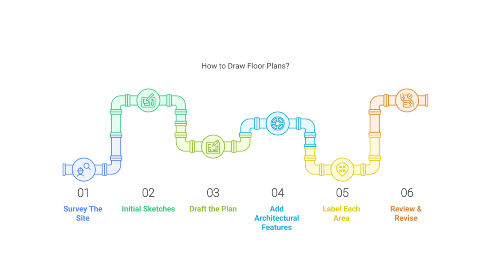
The step-by-step approach to drawing floor plans is as follows:
- Survey The Site: Before starting, measure the existing space carefully. This ensures your design will fit well and helps avoid big mistakes that could affect the final outcome.
- Initial Sketches: Start by sketching rough designs. They don’t need to be perfect. These early drawings help you visualise your ideas and guide you as you work on the final plan.
- Draft the Plan: Create a more detailed and accurate plan showing the size of each room, door, and window. Measure everything carefully, even twice, to ensure it fits correctly.
- Add Architectural Features: Highlight essential elements like stairs, modern appliances, and storage spaces. These features make the space more functional and appealing.
- Label Each Area: Label each room (such as the kitchen, bedroom, and bathroom) and other spaces. This helps prevent confusion when moving furniture or living in the house and makes it easier for visitors or new residents to navigate.
- Review & Revise: Go over the floor plan carefully and make any needed changes. Keep adjusting it until you’re happy with the final design. This ensures everything works as planned.
Creating accurate floor plans is just one part of the architectural drawing process, but several other techniques and strategies can elevate the quality of your work.
Tips for Effective Architectural Drawing
Creating effective architectural drawings requires both technical skill and artistic precision. Whether you’re working on initial sketches or final construction documents, following certain drawing tips can help improve clarity, accuracy, and overall quality.
These tips help make architectural drawings clear, accurate, and efficient, ensuring they effectively communicate design ideas and construction details. Effective tips for architectural drawings are as follows:
- Maintain Consistent Scale: Use the correct scale (like 1:50 for floor plans and 1:10 for details) to ensure accurate dimensions.
- Keep Drawings Clean and Organised: Avoid clutter by keeping layouts clear, sections labelled, and annotations consistent.
- Apply Layering in Digital Drawings: Organise parts like walls, furniture, and measurements in separate layers for easier editing and visibility.
- Use Hatching and Shading Effectively: Add texture and depth with hatching for materials and shading for volume.
- Incorporate Annotations and Dimensions: Clearly label room names, sizes, materials, and section markers to ensure accuracy in construction.
- Ensure Proper Alignment and Proportions: Keep grids, symmetry, and spacing consistent for a balanced look in your drawings.
- Follow Regulatory Standards and Symbols: Use approved symbols for doors, windows, and utilities to meet building codes.
- Improve Presentations with Context Elements: Add elements like trees, people, and furniture to give the scale and realism of your drawing.
- Check for Consistency Across Drawings: Make sure floor plans, elevations, and sections match up and reflect the same details.
- Review and Revise Before Finalising: Double-check for mistakes, missing dimensions, and inconsistencies before finishing the drawings.
BIM Supports GREEN EARTH.

Conclusion
Architectural drawings are essential in transforming design ideas into real, buildable structures. Various types, such as site plans, floor plans, elevations, and sections, are crucial in clearly communicating the design and ensuring accuracy.
Modern tools like CAD software and BIM technology improve precision, simplify workflows, and promote innovation. By embracing these advancements, architects can design more efficient, sustainable, and visually striking buildings while maintaining clarity and practicality in their drawings.
Are you looking for BIM solutions?
BIM ASSOCIATES is your one-stop BIM Solution provider for the Architecture and Structure discipline. Their solutions help clients with better decision-making, cost-saving, efficient construction planning, and green earth initiatives.
You might also like: How Does BIM Help Construction Teams Improve Efficiency and Accuracy?
FAQs (Frequently Asked Questions)
1. What is meant by architectural drawings?
Architectural drawings are sketches, diagrams, or plans used to design, build, and document buildings and structures.
2. What is the purpose of architectural drawings?
Architectural drawings help develop design ideas, communicate concepts, convince clients, and document completed projects.
3. What is the difference between architectural drawing and engineering drawing?
Architectural drawings focus on layout, materials, and finishes while engineering drawings deal with structural changes, such as modifying load-bearing walls.